Table of Contents
Advertisement
Quick Links
Advertisement
Table of Contents

Related Manuals for Jegs IGBT Series


Summary of Contents for Jegs IGBT Series
- Page 1 OWNER'S MANUAL THE IGBT SERIES OF MIG/MAG...
-
Page 2: Table Of Contents
CONTENTS ‐ 1.Safety……………………..………………..…………………………….…..……..……………………………………………………. ‐ 2.General Description……...………..……...…………………….………...………..……………………………………….. 4 ‐3.Main Parameter…….……...…...……..………………………………….…..……….…………………………………… ‐ 4.Structure of welder…….……...…...………………………..…………….…..……….…………………………………… 7 ‐ 5.Installation ……………………………………………………………………………………………………………………………….. ‐ 6.Welding settings quick reference chart………………………………………………………………………………………. ‐ 7.Range of welding current and voltage in CO2 welding...……….…………………………………………………… ‐ 8.Welding parameters table..…....……………………….………..…………………………………………… 20 ‐ 9.Caution……….....…………………………………………...………………..…........‐... -
Page 3: Safety
This welding machine for industrial and professional use is in conformity with IEC974 International Safety Standard. Hereby we state that we provide one year of guarantee for this welding machine since the date of purchase. Please read and understand this instruction manual carefully before the installation and operation of this machine. - Page 4 ∙The switching of function modes while the welding operation is performed, may damage the machine. ∙Disconnect the electrode‐holder cable with the machine, before turning machine on. ∙A safety switch is necessary to prevent the machine from electrical leakage. ∙Welding tools used should be of high quality. ∙Operators should be qualified.
-
Page 5: General Description
2.GENERAL DESCRIPTION This welding machine is composed of the inverter MIG welder power supply with invariable voltage output external characteristics manufactured with advanced IGBT inverter technology. With high‐power component IGBT, the inverter converts the DC voltage, which is rectified from input 50Hz/60Hz AC voltage, to high‐frequency 20KHz AC voltage;... - Page 6 Roller 0.8mm‐0.9mm Operating environment Adequate ventilation is required to provide proper cooling for the MIG‐GS/GD. Ensure that the machine is placed on a stable level surface where clean cool air can easily flow through the unit. The MIG‐GS/GD has electrical components and control circuit boards which will be damaged by excessive dust and dirt, so a clean operating environment is essential Block Diagram IN P U T...
-
Page 7: Main Parameter
3.MAIN PARAMETER BLUEARC‐200MSTI TYPE single‐phase Power supply voltage (V) 220V15% Input current (A) Power supply capacity (KVA) Current adjustment range (A) 50~200 Output voltage (V) 15~24 Rated output current (A) Rated output voltage (V) Rated duty cycle (%) Power factor 0.75 Efficiency (%) Wire feeder type... -
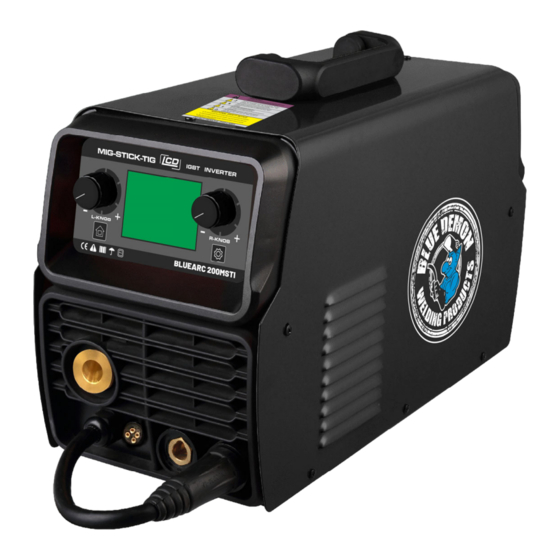
Page 8: Structure Of Welder
4.Structure of welder 1. Left knob / welding mode selection knob/MIG voltage refine 2. Left button/ home button 3. Right knob /Parameter adjust knob 4. Right button / Parameter adjust button /wire speed/diameter/inductance/2T/4T/HOT START/ARC FORCE 5. MIG Torch ‘Euro Style’ Connection Socket 6. -
Page 9: Installation
20. Torch trigger switch 21. Torch “Euro” connector 22. Workpiece earth clamp 23. Earth lead quick connector 24. Conical gas nozzle/shroud 25. Welding tip 26. Shroud spring 27. Tip adapter 25 26 5.INSTALLTION 5.1. MIG Welding Set Up & Operation 5.1.1 Fitting the spool 5.1.1.1 open the cover door for the wire feed compartment. - Page 10 5.1.2.2 check the wire drive roller(16) groove matches the selected MIG wire type and size. The drive roller will have two different sized grooves, the size of the groove in use is stamped on the side of the drive roller. For flux cored ‘soft’ wire ,such as that used in gasless MIG welding, the drive roller groove has a serrated profit.
- Page 11 5.1.4.5 Connect Earth Clamp (22) to the work piece. Contact with workpiece must be strong contact with clean, bare metal, with no corrosion, paint or scale at the contact point. 5.1.4.6 Connect the gas regulator (optional) and gas line to the inlet on the rear panel (11). If the regulator is equipped with a flow gauge, the flow should be set between 8 –...
- Page 12 5.1.5 Controls for MIG welding 5.1.5.1 Switch the machine on using the main power switch (10). Wait 5 seconds for the digital control program to load up. Press the Left button (2) to mode section and select the mode by Left knob (1), press the Left knob (1) to confirm the selection.
- Page 13 5.1.5.4 Press the Right button (4) again to adjust the inductance of the welding arc. Use the Right Knob (3) to adjust the inductance from ‐10 (less inductance) to +10 (more inductance). A quick note regarding inductance – this effectively adjusts the intensity of the welding arc.inductance makes the arc ‘softer’, with less weld spatter.
- Page 14 5.1.5.8 Wire check function: press the Right Button (4) again to enter to the wire check mode, rotate Right knob (3) to select ON/OFF 5.1.6 Feeding the wire 1.6.1 Remove the conical nozzle (24) and the welding tip (25) from the torch. The conical nozzle is removed by turning clockwise and pulling off simultaneously.
- Page 15 5.1.8 Lift TIG operation Note ‐ TIG operation requires an argon gas supply, TIG torch, consumables, and gas regulator. These accessories are not included standard with the MIG‐GS/GD; contact your supplier for further details. 5.1.8.1 Connect Earth Lead Quick Connector (23) to the positive (+) output welding terminal (6). 5.1.8.2 Connect Earth Clamp (22) to the work piece.
-
Page 16: Welding Settings Quick Reference Chart
6. Welding settings quick reference chart... - Page 17 Basic welding guide MIG (GMAW/FCAW) Basic Welding Technique Two different welding processes are covered in this section (GMAW and FCAW), with the intention providing the basic concepts in using the MIG mode of welding, where a welding gun is handheld, and the electrode (welding wire) is fed into a weld puddle, and the arc is shielded by an inert welding grade shielding gas or inert welding grade shielding gas mixture.
- Page 18 Position of MIG Torch The angle of MIG torch to the weld has an effect on the width of the weld The welding gun should be held at an angle to the weld joint. (See Secondary Adjustment Variables below) Hold the gun so that the welding seam is viewed at all times.
- Page 19 Distance from the MIG Torch Nozzle to the Work Piece The electrode wire stick out from the MIG Torch nozzle should be between 10mm to 20.0mm. This distance may vary depending on the type of joint that is being welded Travel Speed The speed at which the molten pool travels influences the width of the weld and penetration of the welding run MIG Welding (GMAW) Variables...
- Page 20 Establishing the Arc and Making Weld Beads Before attempting to weld on a finished piece of work, it is recommended that practice welds be made on a sample metal of the same material as that of the finished piece The easiest welding procedure for the beginner to experiment with MIG welding is the flat position. The equipment is capable of flat, vertical and overhead positions.
-
Page 21: Range Of Welding Current And Voltage In Co2 Welding
7.Range of welding current and voltage in CO welding Short circuit transition Granular transition Wireφ(in) Wireφ(mm) Voltage (V) Voltage (V) Current(A) Current(A) 0.024 40~70 17~19 160~400 25~38 0.030 60~100 18~19 200~500 26~40 0.040 80~120 18~21 200~600 27~40 ‐The option of the welding speed The welding quality and productivity should be taken into consideration for the option of welding speed. - Page 22 17.72~21.65 0.063 0.040 80~100 18~19 10~15 15.75~21.65 10~15 0.079 0~0.020 0.040 100~110 19~20 19.69~21.65 10~15 0.091 0.020~0.040 0.040 or 0.047 110~130 19~20 15.75~19.69 10~15 0.126 0.040~0.047 0.040 or 0.047 130~150 19~21 15.75~19.69 10~15 0.178 0.047~0.059 0.047 150~170 21~23 Parameter for flat fillet welding (Please refer to the following figure.) Plate Welding Welding...
-
Page 23: Caution
Parameter for Lap Welding (Please refer to the following figure.) Plate Welding Welding Welding Welding Wire thickness current voltage speed volume position φ(in) (A) (V) (in/min) (L/min) t(in) 0.032 0.032~0.035 60~70 16~17 15.75~17.72 10~15 0.047 0.040 80~100 18~19 17.72~21.65 10~15 0.040 ~ 0.047 17.72~21.65 0.063... -
Page 24: Maintenance
10.MAINTENANCE 1. Disconnect input plug or power before maintenance or repair on machine. 2. Be sure input ground wire is properly connected to a ground terminal. 3. Check whether the inner gas‐electricity connection is well (esp. the plugs), and tighten the loose connection; if there is oxidization, remove it with sandpaper and then re‐connect. -
Page 25: Daily Checking
11.DAILY CHECKING To make best use of the machine, daily checking is especially important. During the daily checking, please check in the order of torch, wire‐feeding vehicle, all kinds of PCB, the gas hole, and so on. Remove the dust or replace some parts if necessary. - Page 26 11.2. Welding torch Part Check Remarks 1. Check if the nozzle is fixed firmly Possible gas leakage occurs due to the unfixed nozzle. and distortion of the tip exists. Nozzle 2. Check if there is spatter sticking on Spatter possibly leads to the damage of torch. Use the nozzle.
- Page 27 11.3. Wire feeder Part Check Remarks Pressure 1. Check if the pressure‐adjusting handle is The unfixed pressure‐adjusting handle leads adjusting fixed and adjusted to the desired position. to the unstable welding output. handle 1. Check if there is dust or spatter inside the Remove the dust.
-
Page 28: Connection Diagram Of The Machine
12.CONNECTION DIAGRAM OF THE MACHINE... -
Page 29: Explosion Drawing
13.EXPLOSION DRAWING NAME NAME handle rubber support machine cover fixed beam wire spool shaft rectifier diode side plate circuit board support wire feeder thermistor lock IGBT gasket rectifier bridge wire feeder motor block plate wire feeder support main board hinge radiator front control board clapboard... - Page 30 14.IGBT Equipment Warranty Welding Material Sales Effective Jan 1, 2021 Limited Warranty This warranty applies to the original purchaser and is subject to the terms and conditions listed below. This Limited Warranty is for new equipment sold after the above date, providing coverage for defects in material and workmanship at the time it is shipped from the factory.
Need help?
Do you have a question about the IGBT Series and is the answer not in the manual?
Questions and answers