
Related Manuals for ProSoft Technology PLX51-HART-4I


Summary of Contents for ProSoft Technology PLX51-HART-4I
- Page 1 PLX51-HART-4I / PLX51-HART-4O HART Input/Output Multidrop Field Devices July 6, 2022 USER MANUAL...
-
Page 2: Your Feedback Please
Neither ProSoft Technology nor any of its affiliates or subsidiaries shall be responsible or liable for misuse of the information contained herein. Information in this document including illustrations, specifications and dimensions may contain technical inaccuracies or typographical errors. -
Page 3: Table Of Contents
PLX51-HART-4I / PLX51-HART-4O ♦ HART Input/Output Contents Multidrop Field Devices User Manual Contents Your Feedback Please ......................2 Content Disclaimer ........................ 2 Preface Introduction to the PLX51-HART-4x ............5 Features ....................... 6 Architecture ....................7 Additional Information .................. 9 References ....................10 Support ...................... - Page 4 PLX51-HART-4I / PLX51-HART-4O ♦ HART Input/Output Preface Multidrop Field Devices User Manual 4.4.1 Multidrop ....................73 4.4.2 HART Custom Command ................80 PCCC Operation ..................82 4.5.1 Multidrop ....................83 FTView Operation ..................87 4.6.1 Register EDS File ..................87 4.6.2...
-
Page 5: Preface
Preface Introduction to the PLX51-HART-4x The PLX51-HART-4I and PLX51-HART-4O allows the user to interface up to four analog HART channels with either EtherNet/IP, Modbus TCP/IP, DNP3 TCP/UDP, or PCCC (AB-ETH) protocols. This includes 4 to 20 mA input and output devices with or without HART communications, as well as 0 to 20 mA devices without HART. -
Page 6: Features
The PLX51-HART-4I or PLX51-HART-4O module is configured using the PLX50 Configuration Utility. This software can be downloaded from https://www.prosoft- technology.com free of charge. Hereafter the PLX51-HART-4I or PLX51-HART-4O module will be referred to as the module. ProSoft Technology, Inc. Page 6 of 127... -
Page 7: Architecture
Figure 1.2 – PLX51-HART-4I EtherNet/IP typical architecture The figure below provides an example of the typical architecture for a PLX51-HART- 4x interfacing to a Modbus TCP/IP Client. Figure 1.3 – PLX51-HART-4I Modbus TCP/IP typical architecture ProSoft Technology, Inc. Page 7 of 127... - Page 8 The figure below provides an example of the typical architecture for a PLX51-HART- 4I interfacing to a DNP3 Master SCADA. Figure 1.4 – PLX51-HART-4I DNP3 typical architecture The figure below provides an example of the typical architecture for a PLX51-HART- 4I interfacing to a SLC using PCCC.
-
Page 9: Additional Information
PLX51-HART-4I / PLX51-HART-4O ♦ HART Input/Output Preface Multidrop Field Devices User Manual The figure below provides an example of the typical architecture for a PLX51-HART- 4I with multidrop HART devices. Figure 1.6 – PLX51-HART-4I multidrop architecture Additional Information The following documents contain additional information that can assist the user with the module installation and operation. -
Page 10: References
PLX51-HART-4I / PLX51-HART-4O ♦ HART Input/Output Preface Multidrop Field Devices User Manual Table 1.1 - Additional Information Link Resource PLX50 Configuration Utility https://www.prosoft-technology.com/ Installation User Manual, Datasheet https://www.prosoft-technology.com/ Example Code & UDTs www.cisco.com/c/en/us/td/docs/video/cds/cde/cde205_220_420/installati Ethernet wiring standard on/guide/cde205_220_420_hig/Connectors.html References Table 1.2 – References... -
Page 11: Installation
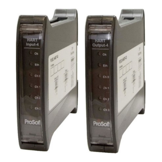
These LEDs are used to provide status of the module system operation, the Ethernet interface, and the status of each of the four analog HART channels. Figure 2.2 – PLX51-HART-4I front and top view ProSoft Technology, Inc. Page 11 of 127... -
Page 12: Module Mounting
PLX51-HART-4I / PLX51-HART-4O ♦ HART Input/Output Installation Multidrop Field Devices User Manual The module provides four DIP switches at the top of the enclosure as shown in the top view figure above. Table 2.1 - DIP Switch Settings Description DIP Switch DIP Switch 1 Used to force the module into “Safe Mode”. -
Page 13: Power
Analog (HART) – Single Device The Analog HART channels are connected using a two-way connector. The input channels (PLX51-HART-4I) are internally loop powered and therefore can be connected directly to the field device signal terminals. Figure 2.6 – PLX51-HART-4I Connection to Field Device (2-wire) ProSoft Technology, Inc. - Page 14 PLX51-HART-4I / PLX51-HART-4O ♦ HART Input/Output Installation Multidrop Field Devices User Manual The output channels (PLX51-HART-4O) source the current directly and therefore can also be connected directly to the field device signal terminals. The input and output channels provide internal current limiting and electronic fuse protection.
- Page 15 Installation Multidrop Field Devices User Manual The PLX51-HART-4I module supports 2-wire (loop-powered) and 4-wire devices in various configurations as illustrated below. Figure 2.10 – Channel Connection - 2-wire – Module Powered Figure 2.11 – Channel Connection - 4-wire – Device Powered Figure 2.12 –...
-
Page 16: Analog (Hart) - Multidrop
HART-4I. As indicated in the diagrams below, the PLX51-HART-4I can support multidrop devices in series with either module-powered or externally-powered configurations. Figure 2.14 – PLX51-HART-4I - Multidrop Wiring – Series – Module Powered ProSoft Technology, Inc. Page 16 of 127... -
Page 17: Parallel Configuration
Multidrop Field Devices User Manual Figure 2.15 – PLX51-HART-4I - Multidrop Wiring – Series – Externally Powered Figure 2.16 – PLX51-HART-4O - Multidrop Wiring – Series Note: It is not recommended to multidrop 4-wire devices unless all devices make use of isolated power supplies. -
Page 18: Ethernet Port
As indicated in the diagrams below, the PLX51-HART-4I can support multidrop devices in parallel with either module-powered or externally-powered configurations. Figure 2.17 – PLX51-HART-4I - Multidrop Wiring – Parallel – Module Powered Figure 2.18 – PLX51-HART-4I - Multidrop Wiring – Parallel – Externally Powered Figure 2.19 –... -
Page 19: Setup
PLX51-HART-4I / PLX51-HART-4O ♦ HART Input/Output Setup Multidrop Field Devices User Manual Setup Install Configuration Software The network setup and configuration of the module is achieved by means of the PLX50 Configuration Utility. This software can be downloaded from: https://www.prosoft-technology.com/. - Page 20 PLX51-HART-4I / PLX51-HART-4O ♦ HART Input/Output Setup Multidrop Field Devices User Manual Within the PLX50 Configuration Utility, the DHCP server can be found under the Tools menu. Figure 3.2 - Selecting DHCP Server Once opened, the DHCP server will listen on all available network adapters for DHCP requests and display their corresponding MAC addresses.
- Page 21 PLX51-HART-4I / PLX51-HART-4O ♦ HART Input/Output Setup Multidrop Field Devices User Manual To assign an IP address, click on the corresponding “Assign” button. The IP Address Assignment window will open. Figure 3.4 - Assigning IP Address The required IP address can then be either entered, or a recently used IP address can be selected by clicking on an item in the Recent List.
- Page 22 PLX51-HART-4I / PLX51-HART-4O ♦ HART Input/Output Setup Multidrop Field Devices User Manual Once the DHCP process has been completed, the network settings can be set using the Ethernet Port Configuration via the Target Browser. The Target Browser can be accessed under the Tools menu.
- Page 23 PLX51-HART-4I / PLX51-HART-4O ♦ HART Input/Output Setup Multidrop Field Devices User Manual All the relevant Ethernet port configuration parameters can be modified using the Port Configuration window. Figure 3.9 - Port Configuration Alternatively, these parameters can be modified using Rockwell Automation’s RSLinx software.
-
Page 24: Creating A New Project
PLX51-HART-4I / PLX51-HART-4O ♦ HART Input/Output Setup Multidrop Field Devices User Manual Creating a New Project Before the user can configure the module, a new PLX50 Configuration Utility project must be created. Under the File menu, select New. Figure 3.10 - Creating a new project A PLX50 Configuration Utility project will be created, showing the Project Explorer tree view. - Page 25 PLX51-HART-4I / PLX51-HART-4O ♦ HART Input/Output Setup Multidrop Field Devices User Manual In the Add New Device window select the PLX51-HART-4I or PLX51-HART-4O and click the Ok button. The configuration of the PLX51-HART-4I or PLX51-HART-4O are almost identical. Figure 3.12 – Selecting a new module The device will appear in the Project Explorer tree as shown below, and its configuration window opened.
-
Page 26: Module Parameters
PLX51-HART-4I / PLX51-HART-4O ♦ HART Input/Output Setup Multidrop Field Devices User Manual Module Parameters The configuration form is divided into multiple tabs to configure the general, communication and channel specific parameters. When downloading this configuration into the module it will be saved in non-volatile memory that persists when the module is powered down. - Page 27 PLX51-HART-4I / PLX51-HART-4O ♦ HART Input/Output Setup Multidrop Field Devices User Manual The general configuration consists of the following parameters: Table 3.1 - General configuration parameters Description Parameter Instance Name This parameter is a user defined name to identify between various modules.
- Page 28 PLX51-HART-4I / PLX51-HART-4O ♦ HART Input/Output Setup Multidrop Field Devices User Manual Figure 3.16 - Channel configuration (PLX51-HART-4O) Each of the channel configuration tabs consist of the following parameters: Table 3.2 - Channel configuration parameters Description Parameter Enable Channel Used to Enable or Disable the entire analog channel.
- Page 29 PLX51-HART-4I / PLX51-HART-4O ♦ HART Input/Output Setup Multidrop Field Devices User Manual Description Parameter When this parameter is set, the process variables of the HART device (PV, Zero HART Data on SV, TV, and FV as well as the units) will be made zero when the Comms Fail communication to the HART device is lost.
-
Page 30: Advanced Mapping
PLX51-HART-4I / PLX51-HART-4O ♦ HART Input/Output Setup Multidrop Field Devices User Manual Description Parameter This configuration is used to determine the behaviour of the output analog signal when communication from the source (EtherNet/IP, DNP3 or Modbus TCP/IP) is lost. Comm Fail Freeze Enabling this option freezes the output value to its last state, when communication is lost. -
Page 31: Diagnostics
PLX51-HART-4I / PLX51-HART-4O ♦ HART Input/Output Setup Multidrop Field Devices User Manual The Advanced Mapping configuration tab consists of the following parameters: Table 3.3 – Advanced Diagnostics parameters Description Parameter Action Diagnostics When the Diagnostics option is selected, the user will be able to configure a specific HART command that must be sent to the “main”... - Page 32 PLX51-HART-4I / PLX51-HART-4O ♦ HART Input/Output Setup Multidrop Field Devices User Manual When using the Diagnostics Action; to create a new Advanced Diagnostic item, select the Build button. The HART Advanced Diagnostic Builder will open. Figure 3.18 – Advanced Diagnostic Builder The builder is used to generate the command, and to define the Data Type.
-
Page 33: Multidrop
PLX51-HART-4I / PLX51-HART-4O ♦ HART Input/Output Setup Multidrop Field Devices User Manual 3.5.2 Multidrop When using the Modbus TCP/IP or PCCC interface protocol, only Multidrop action is supported (see below). The data from each multidrop HART device will be placed at specific Modbus Registers or SLC File numbers (based on the Multidrop Device Index used). -
Page 34: Custom
PLX51-HART-4I / PLX51-HART-4O ♦ HART Input/Output Setup Multidrop Field Devices User Manual 3.5.3 Custom When using the Custom Action the user will need to create the custom HART command to send. To create a new Custom Command item, select the Build button. - Page 35 PLX51-HART-4I / PLX51-HART-4O ♦ HART Input/Output Setup Multidrop Field Devices User Manual Modbus TCP/IP The required HART command and specific Modbus Offsets will need to be entered into the builder window as shown below. Figure 3.22 – Custom HART Command Builder Mapping (for Modbus TCP) Each HART channel is allowed up to 500 bytes of mapping data for custom HART commands.
- Page 36 PLX51-HART-4I / PLX51-HART-4O ♦ HART Input/Output Setup Multidrop Field Devices User Manual Description Modbus Parameter For example, if the source data offset entered is 20 and the custom HART commands is on HART channel 0, then the HART message data to be sent will start at Modbus HR 5020 (HR 5000 for HART channel 0 + offset HR 20).
-
Page 37: Dnp3 Security
PLX51-HART-4I / PLX51-HART-4O ♦ HART Input/Output Setup Multidrop Field Devices User Manual DNP3 Security If one of the DNP3 protocols (DNP3 TCP or DNP3 UDP) have been selected, then the DNP3 Security tab will be enabled. This DNP3 Security configuration consists of the following parameters: Table 3.7 –... - Page 38 PLX51-HART-4I / PLX51-HART-4O ♦ HART Input/Output Setup Multidrop Field Devices User Manual Figure 3.23 – DNP3 security configuration ProSoft Technology, Inc. Page 38 of 127...
-
Page 39: Multidrop
PLX51-HART-4I / PLX51-HART-4O ♦ HART Input/Output Setup Multidrop Field Devices User Manual MultiDrop When using Multidrop and requiring a HART device at a specific address to be the “main” HART device (e.g. which will be populated in the Logix Input Assembly), then the Fixed HART Address parameter must be used (see below). - Page 40 PLX51-HART-4I / PLX51-HART-4O ♦ HART Input/Output Setup Multidrop Field Devices User Manual If needed, the user can set the node address of a module from the PLX50 Configuration Utility as shown below: Figure 3.26 – Set Field Device Node Address Figure 3.27 –...
-
Page 41: Module Download
PLX51-HART-4I / PLX51-HART-4O ♦ HART Input/Output Setup Multidrop Field Devices User Manual Module Download Once the module configuration has been completed, it must be downloaded to the module. Before downloading the Connection Path of the module should be set. This path will automatically default to the IP address of the module, as set in the module configuration. - Page 42 PLX51-HART-4I / PLX51-HART-4O ♦ HART Input/Output Setup Multidrop Field Devices User Manual To initiate the download, right-click on the module and select the Download option. Figure 3.31 - Selecting Download Once complete, the user will be notified that the download was successful.
-
Page 43: Logix Integration
Note: See the next section for importing the configuration (L5X). Figure 3.34 - Add a Generic Ethernet Module in RSLogix 5000 Important: The module configuration for the PLX51-HART-4I and PLX51-HART-4O modules are NOT identical. The user must enter the IP address of the module that will be used. The assembly instance and size must also be added for the input, output, and configuration in the connection parameters section. - Page 44 PLX51-HART-4I / PLX51-HART-4O ♦ HART Input/Output Setup Multidrop Field Devices User Manual Table 3.8 - RSLogix class 1 connection parameters for the PLX51-HART-4I module Assembly Instance Size Connection Parameter Input 119 (32-bit) Output 1 (32-bit) Configuration 0 (8-bit) Figure 3.35 - RSLogix 5000 General module properties for PLX51-HART-4I module...
- Page 45 PLX51-HART-4I / PLX51-HART-4O ♦ HART Input/Output Setup Multidrop Field Devices User Manual Figure 3.36 - RSLogix 5000 General module properties for PLX51-HART-4O module Important: The user will need to enter the exact connection parameters before the module will establish a class 1 connection with the Logix controller.
-
Page 46: Importing Udts And Mapping Routines
(.L5X) file is provided. This file can be imported by right-clicking on an empty rung in the MainRoutine and selecting the Import Rungs option. Figure 3.39 – RSLogix 5000 Importing module specific routine and UDTs Figure 3.40 - Selecting partial import file for PLX51-HART-4I module The import will create the following: •... - Page 47 PLX51-HART-4I / PLX51-HART-4O ♦ HART Input/Output Setup Multidrop Field Devices User Manual The user may need to change the routine to map to the correct module instance name, and make sure that the mapping routine is called by the Program’s Main Routine.
-
Page 48: Operation
1 cyclic communication connection with the module. An input and output assembly is exchanged at the configured (RPI) interval. 4.1.1 Input Assembly The following parameters are used in the input assembly of the PLX51-HART-4I and PLX51-HART-4O modules. Table 4.1 – Logix 5000 input assembly parameters... - Page 49 PLX51-HART-4I / PLX51-HART-4O ♦ HART Input/Output Operation Multidrop Field Devices User Manual Datatype Description Parameter Chx_Tag STRING8 Tag name of the field device. Chx_Descriptor STRING16 Descriptor of the field device. Chx_DeviceStatus SINT Device Status comprising the following bits: Chx_DeviceStatus.LoopOpen BOOL Loop open circuit detected.
- Page 50 PLX51-HART-4I / PLX51-HART-4O ♦ HART Input/Output Operation Multidrop Field Devices User Manual Datatype Description Parameter Chx_HARTStatus.AccessRestricted BOOL Access Restricted. Chx_HARTStatus.DeviceBusy BOOL Device Busy. Chx_HARTStatus.CommandNotImplemented BOOL Command not supported. Chx_HARTStatus.DeviceMalfunction BOOL Device Malfunction. Chx_HARTStatus.ConfigurationChanged BOOL Configuration changed. Chx_HARTStatus.Coldstart BOOL Field device power failure or device reset.
-
Page 51: Output Assembly
PLX51-HART-4I / PLX51-HART-4O ♦ HART Input/Output Operation Multidrop Field Devices User Manual 4.1.2 Output Assembly The following parameters are used in the output assembly of the PLX51-HART-4O module. Table 4.2 – PLX51-HART-4O Logix 5000 output assembly parameters Datatype Description Parameter... - Page 52 PLX51-HART-4I / PLX51-HART-4O ♦ HART Input/Output Operation Multidrop Field Devices User Manual Table 4.3 – Relay HART Message Parameters Value / Description Parameter Message Type CIP Generic Service Type Custom Service Code 79 Hex (Relay HART Message service) Class 40F Hex...
- Page 53 PLX51-HART-4I / PLX51-HART-4O ♦ HART Input/Output Operation Multidrop Field Devices User Manual HART Command Status Encoding The Status code returned in the HART relay command are as follows: Examine the value of the bit 7 in the first byte. ProSoft Technology, Inc.
- Page 54 PLX51-HART-4I / PLX51-HART-4O ♦ HART Input/Output Operation Multidrop Field Devices User Manual Table 4.6 - Status Decoding (when first byte bit 7 = 0) If Byte 0 Bit 7 = 0 then: First Byte : Command Errors Value Description No error...
- Page 55 PLX51-HART-4I / PLX51-HART-4O ♦ HART Input/Output Operation Multidrop Field Devices User Manual Figure 4.3 – Relay HART Message Example Configuration Figure 4.4 – Relay HART Command Example – Request ProSoft Technology, Inc. Page 55 of 127...
- Page 56 PLX51-HART-4I / PLX51-HART-4O ♦ HART Input/Output Operation Multidrop Field Devices User Manual Figure 4.5 – Relay HART Command Example – Response Note: The HART Long Address for a device is comprised of the Manufacturer ID, Device Type Code and Device ID. These values are displayed on the Channel Status screen in the PLX50 Configuration Utility when the device is Online.
-
Page 57: Multidrop
PLX51-HART-4I / PLX51-HART-4O ♦ HART Input/Output Operation Multidrop Field Devices User Manual 4.1.4 Multidrop When using Multidrop HART devices with Logix, the user must select the Logix Tag to be used to populate the HART device data. The user can either select to use the current Multidrop tag structure or the legacy MVI56Legacy tag structure. - Page 58 PLX51-HART-4I / PLX51-HART-4O ♦ HART Input/Output Operation Multidrop Field Devices User Manual MultiDrop UDT Structure Figure 4.7 – Multidrop – UDT Table 4.8 – Multidrop UDT structure Datatype Description Parameter PollStatus SINT Bit 0 – When set this bit will indicate that the device is...
- Page 59 PLX51-HART-4I / PLX51-HART-4O ♦ HART Input/Output Operation Multidrop Field Devices User Manual Datatype Description Parameter DeviceRevision SINT Device Revision Number. SoftwareRevision SINT Software Revision Number. HardwareRevision SINT Hardware Revision Number. DeviceFlags SINT Device Function Flags. Bit 0 – Multi Sensor device Bit 1 –...
- Page 60 PLX51-HART-4I / PLX51-HART-4O ♦ HART Input/Output Operation Multidrop Field Devices User Manual MultiDrop Legacy (MVI56) UDT Structure Figure 4.8 – Multidrop – Legacy UDT Table 4.9 – Multidrop UDT structure Datatype Description Parameter Auto_Poll_CMD_Status SINT Bit 0 – When set this bit will indicate that the device...
-
Page 61: Hart Channel Command
PLX51-HART-4I / PLX51-HART-4O ♦ HART Input/Output Operation Multidrop Field Devices User Manual Datatype Description Parameter Bit 0 – Multi Sensor device Bit 1 – EEPROM control required Bit 2 – Protocol Bridge Device Device_ID SINT[3] Device Identification Number Min_Preambles_Resp SINT Number of Preambles. - Page 62 PLX51-HART-4I / PLX51-HART-4O ♦ HART Input/Output Operation Multidrop Field Devices User Manual Value / Description Parameter Message Type CIP Generic Service Type Set Single Attribute Service Code 10 Hex (Set Single Attribute) Class 40F Hex Instance Channel value + 1...
-
Page 63: Hart Process Variable Cip Parameters
PLX51-HART-4I / PLX51-HART-4O ♦ HART Input/Output Operation Multidrop Field Devices User Manual 4.1.6 HART Process Variable CIP Parameters The module supports additional CIP attributes which will allow the EtherNet/IP device to read all 4 process variables (PV, SV, TV, and FV) from the “main” HART device as well as each multidrop HART device for each respective HART channel. -
Page 64: Hart Custom Command
PLX51-HART-4I / PLX51-HART-4O ♦ HART Input/Output Operation Multidrop Field Devices User Manual 4.1.7 HART Custom Command The module supports sending of custom HART commands to a field device. See the Advanced Mapping setup section for more details regarding the Custom Command parameters. - Page 65 PLX51-HART-4I / PLX51-HART-4O ♦ HART Input/Output Operation Multidrop Field Devices User Manual Below is the description of the various parameters in the UDT. Table 4.12 – Custom HART command UDT Parameters Description Parameter MsgTrigger This is the trigger to start the execution of the custom HART command.
-
Page 66: Dnp3 Operation
PLX51-HART-4I / PLX51-HART-4O ♦ HART Input/Output Operation Multidrop Field Devices User Manual DNP3 Operation The DNP3 operation is enabled when the configuration protocol is set to either DNP3 TCP or DNP3 UDP. The module will then operate as a DNP3 Outstation supporting the following DNP3 objects. - Page 67 PLX51-HART-4I / PLX51-HART-4O ♦ HART Input/Output Operation Multidrop Field Devices User Manual Functions: Read Item Parameter Length General Channel 0 Channel 1 Channel 2 Channel 3 Module Status Bit 0 – Configuration Valid Bit 1 – Channel 0 Enabled Bit 2 – Channel 1 Enabled Bit 3 –...
-
Page 68: Dnp3 Security
PLX51-HART-4I / PLX51-HART-4O ♦ HART Input/Output Operation Multidrop Field Devices User Manual 4.3.1 DNP3 Security DNP3 offers Secure Authentication for links at risk of being attacked. There are various Key Change methods, Message Authentication Code (MAC) algorithms, and Authentication methods provided in the DNP3 protocol specification. -
Page 69: Modbus Tcp/Ip Operation
PLX51-HART-4I / PLX51-HART-4O ♦ HART Input/Output Operation Multidrop Field Devices User Manual Modbus TCP/IP Operation The Modbus TCP/IP operation is enabled when the configuration protocol is set to Modbus TCP/IP. The module will then operate as a Modbus TCP/IP Server supporting the following Modbus registers for the main device. - Page 70 PLX51-HART-4I / PLX51-HART-4O ♦ HART Input/Output Operation Multidrop Field Devices User Manual Channel 2 Live List When using Multidrop functionality this will indicate which of the configured devices are online. Note that each bit represents the configured Multidrop Device Index (see the Multidrop configuration in the Advanced Mapping section).
- Page 71 PLX51-HART-4I / PLX51-HART-4O ♦ HART Input/Output Operation Multidrop Field Devices User Manual Date BYTE[3] HART Statistics HART Tx Count DINT HART Rx Count DINT Communication Errors DINT Command Errors DINT Parity Errors DINT Output Data - Note: These are Write-Only Registers...
- Page 72 PLX51-HART-4I / PLX51-HART-4O ♦ HART Input/Output Operation Multidrop Field Devices User Manual Device Status Bit 0 – LoopOpen Loop open circuit detected. (Current < 3.6 mA) Bit 1 – CurrentUnderrange Loop current under range. (Current < 3.8 mA) Bit 2 – CurrentOverrange Loop current over range.
-
Page 73: Multidrop
PLX51-HART-4I / PLX51-HART-4O ♦ HART Input/Output Operation Multidrop Field Devices User Manual 4.4.1 Multidrop When multidrop is being used for HART devices the data from each device will automatically be updated to the specific Multidrop Device Index (MD). The table below indicates the Modbus location for the associated data. - Page 74 PLX51-HART-4I / PLX51-HART-4O ♦ HART Input/Output Operation Multidrop Field Devices User Manual Descriptor BYTE[16] 1022 2022 3022 4022 Date BYTE[3] 1030 2030 3030 4030 Multidrop Device Index (MD) - 1 Poll Status Bit 0 – Online 1100 2100 3100 4100...
- Page 75 PLX51-HART-4I / PLX51-HART-4O ♦ HART Input/Output Operation Multidrop Field Devices User Manual Device ID Number BYTE[3] 1205 2205 3205 4205 Pad Byte BYTE Preamble Response BYTE 1207 2207 3207 4207 Max Number of Device Vars BYTE Config Change Count 1208...
- Page 76 PLX51-HART-4I / PLX51-HART-4O ♦ HART Input/Output Operation Multidrop Field Devices User Manual Multidrop Device Index (MD) – 4 Poll Status Bit 0 – Online 1400 2400 3400 4400 When set this bit will indicate that the device is online Manufacturer ID...
- Page 77 PLX51-HART-4I / PLX51-HART-4O ♦ HART Input/Output Operation Multidrop Field Devices User Manual Preamble Response BYTE 1507 2507 3507 4507 Max Number of Device Vars BYTE Config Change Count 1508 2508 3508 4508 Extended Device Status BYTE 1509 2509 3509 4509...
- Page 78 PLX51-HART-4I / PLX51-HART-4O ♦ HART Input/Output Operation Multidrop Field Devices User Manual Byte Date Channel Channel Channel Channel General Length Type Multidrop Device Index (MD) - 0 REAL 1000 2000 3000 4000 REAL 1002 2002 3002 4002 REAL 1004 2004...
- Page 79 PLX51-HART-4I / PLX51-HART-4O ♦ HART Input/Output Operation Multidrop Field Devices User Manual FV units code SINT Multidrop Device Index (MD) - 5 REAL 1500 2500 3500 4500 REAL 1502 2502 3502 4502 REAL 1504 2504 3504 4504 REAL 1506 2506...
-
Page 80: Hart Custom Command
PLX51-HART-4I / PLX51-HART-4O ♦ HART Input/Output Operation Multidrop Field Devices User Manual 4.4.2 HART Custom Command The module supports sending of custom HART commands to a field device. See the Advanced Mapping setup section for more details regarding the Custom Command parameters. - Page 81 PLX51-HART-4I / PLX51-HART-4O ♦ HART Input/Output Operation Multidrop Field Devices User Manual Source Data Offset The source data offset parameter is the location in the Modbus HR range where the HART data to be sent is stored. For example, if the source data offset entered is 20 and the custom HART commands is on HART channel 0, then the HART message data to be sent will start at Modbus HR 5020 (HR 5000 for HART channel 0 + offset HR 20).
-
Page 82: Pccc Operation
PLX51-HART-4I / PLX51-HART-4O ♦ HART Input/Output Operation Multidrop Field Devices User Manual PCCC Operation The PCCC operation is enabled when the configuration protocol is set to SLC 500 / MicroLogix / PLC5. The module will then operate as a PCCC (AB-ETH) Slave allowing SLC500, MicroLogix, and PLC5 controllers to read and write data to the HART devices. -
Page 83: Multidrop
PLX51-HART-4I / PLX51-HART-4O ♦ HART Input/Output Operation Multidrop Field Devices User Manual HART Comms Inhibit N10:59 N11:59 N12:59 N13:59 When set to 1 the HART communication for the specific HART channel will be inhibited. Floats PV Value F20:0 F21:0 F22:0... - Page 84 PLX51-HART-4I / PLX51-HART-4O ♦ HART Input/Output Operation Multidrop Field Devices User Manual TV Unit N10:15 N11:15 N12:15 N13:15 FV Unit N10:16 N11:16 N12:16 N13:16 Multidrop Device Index (MD) - 1 Poll Status N10:17 N11:17 N12:17 N13:17 Bit 0 – When set this bit will indicate that the...
- Page 85 PLX51-HART-4I / PLX51-HART-4O ♦ HART Input/Output Operation Multidrop Field Devices User Manual FV Unit N10:44 N11:44 N12:44 N13:44 Multidrop Device Index (MD) - 5 Poll Status N10:45 N11:45 N12:45 N13:45 Bit 0 – When set this bit will indicate that the...
- Page 86 PLX51-HART-4I / PLX51-HART-4O ♦ HART Input/Output Operation Multidrop Field Devices User Manual Multidrop Device Index (MD) - 4 PV Value F20:26 F21:26 F22:26 F23:26 SV Value F20:27 F21:27 F22:27 F23:27 TV Value F20:28 F21:28 F22:28 F23:28 FV Value F20:29 F21:29...
-
Page 87: Ftview Operation
PLX51-HART-4I / PLX51-HART-4O ♦ HART Input/Output Operation Multidrop Field Devices User Manual FTView Operation The module supports direct EDS parameter access allowing FTView to read main and multidrop process variables directly. 4.6.1 Register EDS File Before FTView can access the HART data from the module, the module’s EDS file must be registered on that system. -
Page 88: Configure Ftview Communication
PLX51-HART-4I / PLX51-HART-4O ♦ HART Input/Output Operation Multidrop Field Devices User Manual 4.6.2 Configure FTView Communication Within the FTView environment, (either SE or ME,) using either a new or existing project ensure that the RSLinx Enterprise server has been added. - Page 89 PLX51-HART-4I / PLX51-HART-4O ♦ HART Input/Output Operation Multidrop Field Devices User Manual The RSLinx Enterprise item will then appear in the FTView project tree. Right-click on the Communication Setup option under this item. Figure 4.19 – Open Communication Setup The Communication Setup window, allows the user to associate a Device Shortcut to the physical module.
-
Page 90: Displaying Process Variables
PLX51-HART-4I / PLX51-HART-4O ♦ HART Input/Output Operation Multidrop Field Devices User Manual A warning, similar to the one below, will be shown. Select the Yes option to continue and accept the changes. Figure 4.21 – Confirm RSLinx Enterprise shortcut 4.6.3 Displaying Process Variables A Numeric Display can now be added to a FTView display to show a HART module parameter. - Page 91 PLX51-HART-4I / PLX51-HART-4O ♦ HART Input/Output Operation Multidrop Field Devices User Manual The FTView Tag Browser will open. A refresh will be required the first time the Tag Browser is opened after any changes have been to the communication setup. Right- click on the Folders tree on the left and select the Refresh All Folders option.
- Page 92 PLX51-HART-4I / PLX51-HART-4O ♦ HART Input/Output Operation Multidrop Field Devices User Manual For a process variable, as in this example, it may be beneficial to set the format to Floating Point and select a suitable number of Decimal Places. Figure 4.25 – Configure Numeric Display The Numeric Display can be tested by using FTView’s Test Display option.
-
Page 93: Diagnostics
PLX51-HART-4I / PLX51-HART-4O ♦ HART Input/Output Diagnostics Multidrop Field Devices User Manual Diagnostics LEDs The module provides six LEDs for diagnostics purposes as shown in the front view figure below. A description of each LED is given in the table below. -
Page 94: Module Status Monitoring In The Plx50 Configuration Utility
PLX51-HART-4I / PLX51-HART-4O ♦ HART Input/Output Diagnostics Multidrop Field Devices User Manual Table 5.1 - Module LED operation Description Module The module LED will provide information regarding the system-level operation of the module. Thus, if the LED is red then the module is not operating correctly. - Page 95 PLX51-HART-4I / PLX51-HART-4O ♦ HART Input/Output Diagnostics Multidrop Field Devices User Manual The Online mode is indicated by the green circle behind the module in the Project Explorer tree. Figure 5.3 - Selecting online Status The Status monitoring window can be opened by either double-clicking on the Status item in the Project Explorer tree, or by right-clicking on the module and selecting Status.
-
Page 96: Ethernet/Ip Status
PLX51-HART-4I / PLX51-HART-4O ♦ HART Input/Output Diagnostics Multidrop Field Devices User Manual The General tab displays the following general parameters and can also be used to set the module time to the PC time: Table 5.2 - Parameters displayed in the Status Monitoring – General Tab... -
Page 97: Logix Statistics
PLX51-HART-4I / PLX51-HART-4O ♦ HART Input/Output Diagnostics Multidrop Field Devices User Manual Class 1 Forward Open The number of Class 1 Forward Open (connection establishment) Count messages sent. Class 3 Forward Open The number of Class 3 Forward Open (connection establishment) Count messages sent. - Page 98 PLX51-HART-4I / PLX51-HART-4O ♦ HART Input/Output Diagnostics Multidrop Field Devices User Manual ENIP Failures This count increases when the ENIP Retry Limit is reached and no response has been received from the Logix Controller. Tag Access General This count increases when a tag cannot be accessed for any other Errors reason not reported above.
-
Page 99: Dnp3 Statistics
PLX51-HART-4I / PLX51-HART-4O ♦ HART Input/Output Diagnostics Multidrop Field Devices User Manual 5.2.3 DNP3 Statistics The DNP3 Statistics will be displayed if either of the two DNP3 protocols have been configured. Figure 5.7 - DNP3 Statistics Table 5.5 – DNP3 statistics... - Page 100 PLX51-HART-4I / PLX51-HART-4O ♦ HART Input/Output Diagnostics Multidrop Field Devices User Manual Description Statistic DNP3 Request Too Many Objects The Hart 4 module supports a maximum of 10 DNP3 objects in a single DNP3 request. This statistic indicates that more than 10 DNP3 objects were found in a single request.
-
Page 101: Security Statistics
PLX51-HART-4I / PLX51-HART-4O ♦ HART Input/Output Diagnostics Multidrop Field Devices User Manual 5.2.4 Security Statistics The DNP3 Security Statistics will be displayed if either of the two DNP3 protocols have been configured. Figure 5.8 - DNP3 Security Statistics Table 5.6 – DNP3 Security statistics... -
Page 102: Modbus
PLX51-HART-4I / PLX51-HART-4O ♦ HART Input/Output Diagnostics Multidrop Field Devices User Manual 5.2.5 Modbus The Modbus Statistics will be displayed if the Modbus TCP/IP protocol has been configured. Figure 5.9 - Modbus Statistics ProSoft Technology, Inc. Page 102 of 127... -
Page 103: Pccc
PLX51-HART-4I / PLX51-HART-4O ♦ HART Input/Output Diagnostics Multidrop Field Devices User Manual Table 5.7 – Modbus statistics Description Statistic Tx Packet Count The number of Modbus packets sent by the module. Rx Packet Count The number of Modbus packets received by the module. - Page 104 PLX51-HART-4I / PLX51-HART-4O ♦ HART Input/Output Diagnostics Multidrop Field Devices User Manual Figure 5.10 - PCCC Statistics ProSoft Technology, Inc. Page 104 of 127...
-
Page 105: Channel Status
PLX51-HART-4I / PLX51-HART-4O ♦ HART Input/Output Diagnostics Multidrop Field Devices User Manual Table 5.8 – PCCC statistics Description Statistic Connection Requests The number of PCCC connection establishment requests received. Read Requests The number of Read requests received. Write Requests The number of Write requests received. - Page 106 PLX51-HART-4I / PLX51-HART-4O ♦ HART Input/Output Diagnostics Multidrop Field Devices User Manual Figure 5.12 - Channel Status – General Table 5.9 - Channel Status Parameters – General Description Parameter The user tag name configured in the field device. (8 characters) Status The current status of the HART communication.
- Page 107 PLX51-HART-4I / PLX51-HART-4O ♦ HART Input/Output Diagnostics Multidrop Field Devices User Manual Figure 5.13 - Channel Status – Device Info Table 5.10 - Channel Status Parameters – Device Info Description Parameter Manufacturer ID The field device manufacturer unique identification code.
- Page 108 PLX51-HART-4I / PLX51-HART-4O ♦ HART Input/Output Diagnostics Multidrop Field Devices User Manual Figure 5.14 - Channel Status – Device Status Table 5.11 - Channel Status Parameters – Device Status Description Parameter Loop Open / Current Fault Flagged if the current loop is either below 3.6mA or above 21.0 mA.
- Page 109 PLX51-HART-4I / PLX51-HART-4O ♦ HART Input/Output Diagnostics Multidrop Field Devices User Manual The Device Configuration tab provides the facility to display and modify common HART parameters in the field device. Figure 5.15 - Channel Status – Device Configuration Table 5.12 - Channel Status Parameters – Device Configuration...
- Page 110 PLX51-HART-4I / PLX51-HART-4O ♦ HART Input/Output Diagnostics Multidrop Field Devices User Manual Figure 5.16 - Updating Device Parameters The Advanced Status tab displays the advanced and device specific status information of the field device. Due to the manufacturer specific encoding of these parameters, consult the field device manufacturer’s documentation for more...
- Page 111 PLX51-HART-4I / PLX51-HART-4O ♦ HART Input/Output Diagnostics Multidrop Field Devices User Manual Figure 5.18 - Channel Status – HART Communication Statistics Table 5.13 - Channel Status Parameters HART Communication Statistics Description Parameter Tx Packet Count The number of HART packets sent.
- Page 112 PLX51-HART-4I / PLX51-HART-4O ♦ HART Input/Output Diagnostics Multidrop Field Devices User Manual The module is capable of storing up to 1000 trend points which are sampled at a user-configurable interval. The user can choose between one of the following sources: •...
-
Page 113: Device List
PLX51-HART-4I / PLX51-HART-4O ♦ HART Input/Output Diagnostics Multidrop Field Devices User Manual Device List The module supports scanning a channel to determine at which short address the field device(s) are. The user can select the start and end address to minimize the scan time. -
Page 114: Multidrop
PLX51-HART-4I / PLX51-HART-4O ♦ HART Input/Output Diagnostics Multidrop Field Devices User Manual MultiDrop The MultiDrop tab will have all the configured multidrop devices, their Status, as well as the four process variables for each multidrop HART device. Figure 5.23 – Channel Status – MultiDrop... -
Page 115: Plx51-Hart-4I Calibration
PLX51-HART-4I / PLX51-HART-4O ♦ HART Input/Output Diagnostics Multidrop Field Devices User Manual 5.6.1 PLX51-HART-4I Calibration: To re-calibrate a PLX51-HART-4I module, Using an external milliamp source, adjust the current to 4 mA, or as close as possible to 4 mA. Enter the exact milliamp value, read from an external meter, into the Low Value Actual numeric inputs. -
Page 116: Plx51-Hart-4O Calibration
PLX51-HART-4I / PLX51-HART-4O ♦ HART Input/Output Diagnostics Multidrop Field Devices User Manual 5.6.2 PLX51-HART-4O Calibration: To re-calibrate a PLX51-HART-4O module: Ensure the channel configuration has both the Prog/Fault Freeze and Comm Fail Freeze options checked, and that the module is disconnected from the EtherNet/IP (Logix), DNP3 or Modbus source. -
Page 117: Module Event Log
PLX51-HART-4I / PLX51-HART-4O ♦ HART Input/Output Diagnostics Multidrop Field Devices User Manual Module Event Log The module logs various diagnostic records to an internal event log. These logs are stored in non-volatile memory and can be displayed using the PLX50 Configuration Utility or via the web interface. -
Page 118: Web Server
PLX51-HART-4I / PLX51-HART-4O ♦ HART Input/Output Diagnostics Multidrop Field Devices User Manual Web Server The module provides a web server allowing a user without the PLX50 Configuration Utility or RSLogix 5000 to view various diagnostics of the module. This includes Ethernet parameters, system event log, advanced diagnostics, and application diagnostics. -
Page 119: Hart Packet Capture
PLX51-HART-4I / PLX51-HART-4O ♦ HART Input/Output Diagnostics Multidrop Field Devices User Manual HART Packet Capture The PLX51-HART-4x module provides the capability to capture the HART traffic for analysis. This will assist you and the support team to diagnose any possible issues. - Page 120 PLX51-HART-4I / PLX51-HART-4O ♦ HART Input/Output Diagnostics Multidrop Field Devices User Manual Figure 5.32 – HART Packet Capture complete The captured HART packets are tabulated as follows: Table 5.14 – HART Packet Capture fields Description Statistic Index The packet index, incremented for each packet sent or received.
-
Page 121: Asset Management Fdt - Dtm Technology
PLX51-HART-4I / PLX51-HART-4O ♦ HART Input/Output Asset Management FDT – DTM Technology Multidrop Field Devices User Manual Asset Management FDT – DTM Technology The module supports FDT / DTM technology, allowing the user to configure any field device using its DTM (Device Type Manager) in any standard FDT Frame (Field Device Tool). -
Page 122: What Is Hart
PLX51-HART-4I / PLX51-HART-4O ♦ HART Input/Output What is HART? Multidrop Field Devices User Manual What is HART? Introduction to HART HART is an acronym for Highway Addressable Remote Transducer. HART is able to transfer digital information across a standard 4-20 mA loop, by superimposing the digital data on the analog signal using Frequency Shift Keying (FSK). -
Page 123: Hart Response Status
PLX51-HART-4I / PLX51-HART-4O ♦ HART Input/Output What is HART? Multidrop Field Devices User Manual HART Response Status Table 7.1 - Status Decoding (when first byte bit 7 = 0) If Byte 0 Bit 7 = 0 then: First Byte : Command Errors... -
Page 124: Technical Specifications
PLX51-HART-4I / PLX51-HART-4O ♦ HART Input/Output Technical Specifications Multidrop Field Devices User Manual Technical Specifications Dimensions Below are the enclosure dimensions as well as the required DIN rail dimensions. All dimensions are in millimeters. Figure 8.1 – Module enclosure dimensions ProSoft Technology, Inc. -
Page 125: Electrical
160mA @ 12 VDC - With 4 field devices at 22mA each. Power consumption 0.9 W – With no field devices attached. 3.1 W – With 4 field devices at 22mA each. 4.3 W – With input channels shorted. (PLX51-HART-4I) Connector (Power) 3-way terminal Connector (Analog) -
Page 126: Analog Output Channel (Plx51-Hart-4O)
PLX51-HART-4I / PLX51-HART-4O ♦ HART Input/Output Technical Specifications Multidrop Field Devices User Manual Analog Output Channel (PLX51-HART-4O) Table 8.4 - Analog Output channel specification Rating Specification Number of channels DAC resolution 16 bit Drive 50 – 1170 Ω Resistive < 50 mH Inductive Accuracy (calibrated 25°C) -
Page 127: Support, Service & Warranty
• • Details about the interfaced serial, Ethernet or Fieldbus devices Note: For technical support calls within the United States, ProSoft Technology’s 24/7 after-hours phone support is available for urgent plant-down issues. Europe / Middle East / Africa Regional Office North America (Corporate Location) Phone: +1.661.716.5100...
Need help?
Do you have a question about the PLX51-HART-4I and is the answer not in the manual?
Questions and answers