Table of Contents
Advertisement
Quick Links
Advertisement
Table of Contents

Subscribe to Our Youtube Channel
Related Manuals for ProSoft Technology BM-0900-GM1K


Summary of Contents for ProSoft Technology BM-0900-GM1K
- Page 1 Multipoint Wireless I/O System January 8, 2018 USER MANUAL...
-
Page 3: Your Feedback Please
January 8, 2018 ® ProSoft Technology Product Documentation In an effort to conserve paper, ProSoft Technology no longer includes printed manuals with our product shipments. These product documentation files may also be freely downloaded from our web site: http://www.prosoft-technology.com ProSoft Technology, Inc. - Page 4 Wireless I/O System User Manual Page 4 of 101 ProSoft Technology, Inc. January 8, 2018...
-
Page 5: Table Of Contents
Active Low 24 VDC Input to Wireless I/O DIO System ........... 24 4-20 mA Wireless I/O System Wiring and External Power Switch Position .... 25 4-20mA Wireless I/O System Wiring and Internal Power Switch Position ....26 ProSoft Technology, Inc. Page 5 of 101 January 8, 2018... - Page 6 Modbus Master Function ..................76 Saving the Project File to the Gateway ..............83 9.10 Retrieving the Project File from the Gateway ............85 9.11 Wireless Site Security Key ..................86 Page 6 of 101 ProSoft Technology, Inc. January 8, 2018...
- Page 7 User Manual Troubleshooting General Maintenance Glossary Support, Service & Warranty 13.1 Warranty Information ..................... 101 ProSoft Technology, Inc. Page 7 of 101 January 8, 2018...
-
Page 9: Preface
Multipoint Wireless I/O radios (Gateways). This document also describes how to maintain and troubleshoot the device. If you have any questions about this product, please call or email: ProSoft Technology, Inc. 9201 Camino Media, Suite #200 Bakersfield, CA 93311... -
Page 10: Document Revision Level
Note: This equipment is suitable for use in Class I, Division 2 Groups A, B, C, and D or non- hazardous locations only Document Revision Level This section provides a history of the revision changes to this document. Page 10 of 101 ProSoft Technology, Inc. January 8, 2018... -
Page 11: Compliance
This BM-0900-GM1K and BM-2400-GM1K complies with Part 15 of the FCC Rules. Operation is subject to the following two conditions: 1) this device may not cause harmful interference, and 2) this device must accept any interference received, including interference that may cause undesired operation. -
Page 12: Certifications
Power leads to terminals must be a maximum of 1 meter in length. IECEx SIR 15.0055X, Ex nA nC IIC, T4 Gc Tamb: -20 ˚C to +80 ˚C Power Supply: 9-30 VDC (24V Typical) 0.25A Peak, 0.20 Continuous Page 12 of 101 ProSoft Technology, Inc. January 8, 2018... -
Page 13: Product & System Overview
- Modbus Master or Slave - 1920 Modbus Register Holding Table • Ordered as a Kit: Includes DataRail® and Mounting Hardware • 35 mm DIN Rail Required for Mounting (Sold Separately) ProSoft Technology, Inc. Page 13 of 101 January 8, 2018... - Page 14 Product & System Overview Page 14 of 101 ProSoft Technology, Inc. January 8, 2018...
-
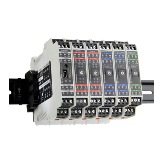
Page 15: Hardware Overview
Product & System Overview Hardware Overview ProSoft Technology, Inc. Page 15 of 101 January 8, 2018... -
Page 16: Items Required For Setup
Screwdriver Set including Technician’s Screwdriver, Adjustable Wrench Any Other Tools Depending on Site and Equipment 2.3.8 Internet Access Internet access required for downloading Software, Firmware, or Documents Page 16 of 101 ProSoft Technology, Inc. January 8, 2018... -
Page 17: Configuration/Installation Sequence
10. Identify COM Port for use in Wireless I/O Designer (Device Manager). 11. Select a Gateway in Project Tree. 12. Update Gateway with Project File. 13. Confirm Gateway Configuration Download OK in Build Tab Window. ProSoft Technology, Inc. Page 17 of 101 January 8, 2018... -
Page 18: Installation
Long blink + 5 short blinks Device Failure Continuous short blinks When device failure has occurred try following actions: Check power source Replace radio module Call Tech Support Page 18 of 101 ProSoft Technology, Inc. January 8, 2018... -
Page 19: Wiring Diagrams (Serial And Power)
Please use the following wiring diagrams and jumper settings to connect a third- party device to the Wireless Gateway. Serial/RTU Port and Power For CE certification, the power leads to the terminals must be a maximum of 1 meter in length. ProSoft Technology, Inc. Page 19 of 101 January 8, 2018... -
Page 20: Grounding Best Practices
être de niveau avec ou au-dessous du niveau du sol. Si la fin du sol et le conducteur l'attachement de l'électrode de mise à la terre sont au dessus du sol, assurer une protection contre les dommages physiques. Page 20 of 101 ProSoft Technology, Inc. January 8, 2018... -
Page 21: Grounding Gateways
CAUTION: Ensure field wiring connections are in accordance with Article 504 of the National Electrical Code, ANSI/NFPA70. For more details on proper grounding electrodes and grounding electrode conductors, consult the National Electrical Code. ProSoft Technology, Inc. Page 21 of 101 January 8, 2018... - Page 22 à la terre pour assurer un bon sol. La méthode de mise à la terre la plus efficace est la connexion directe à la terre avec une impédance minimale. Une impédance inférieure à 5 Ohms recommandée. Page 22 of 101 ProSoft Technology, Inc. January 8, 2018...
-
Page 23: Wiring Examples
Arrival Sensor (Externally Powered PCS Ferguson 3DSO & PCS MT-020) Solenoid (ASCO Red Hat EF8314H301) Connection to the Wireless I/O System. Active High 0-30V Input to Wireless I/O System ProSoft Technology, Inc. Page 23 of 101 January 8, 2018... -
Page 24: Active Low 24 Vdc Input To Wireless I/O Dio System
Wiring Examples Active Low 24 VDC Input to Wireless I/O DIO System Page 24 of 101 ProSoft Technology, Inc. January 8, 2018... -
Page 25: Ma Wireless I/O System Wiring And External Power Switch Position
This application involves the AI of a 4-20mA output device (or 4-20mA output signal) wired to a 4-20mA module at AI+ on bank A. Then, using a DMM, measuring the 4-20mA output on bank B. ProSoft Technology, Inc. Page 25 of 101 January 8, 2018... -
Page 26: 4-20Ma Wireless I/O System Wiring And Internal Power Switch Position
This application involves the AI of a 4-20mA output device (or 4-20mA output signal) wired to a 4-20mA module at AI+ on bank A. Then, using a DMM, measuring the 4-20mA output on bank B. Page 26 of 101 ProSoft Technology, Inc. January 8, 2018... - Page 27 Wiring Examples ProSoft Technology, Inc. Page 27 of 101 January 8, 2018...
- Page 28 Page 28 of 101 ProSoft Technology, Inc. January 8, 2018...
-
Page 29: Installation
état et offre une connexion sécurisée et mécaniquement retenu. IV. Protection contre les transitoires doivent être fournis sur la fourniture de limiter les transitoires à un maximum de 42 Vpk. ProSoft Technology, Inc. Page 29 of 101 January 8, 2018... -
Page 30: Outdoor Enclosure Installation
8. Make/drill a hole on the bottom of the enclosure to run wires. (user must supply own O-ring/sealing) 9. Run conduit for power and antenna cable. 10. Connect antenna cable to antenna and then feed cable into enclosure. 11. Feed power wiring into enclosure. Page 30 of 101 ProSoft Technology, Inc. January 8, 2018... -
Page 31: Wio Gateway And I/O Module(S) Assembly
1. Securely attach DataRail onto a 35 mm x 7.5 mm DIN rail by gently pressing on all four (4) corner clips. CAUTION: Must attach DataRail with arrow pointing up. ProSoft Technology, Inc. Page 31 of 101 January 8, 2018... - Page 32 3) Drilling a hole may be required for routing antenna cable – use 5/16” or larger diameter, user must supply own O-ring/sealing 4) Use proper fittings to seal hole for antenna cable Page 32 of 101 ProSoft Technology, Inc. January 8, 2018...
- Page 33 ID(s). Each of the Modules must be set to its own ID for the system to function properly. Enter this ID when configuring that Module in the Wireless I/O Designer software. ProSoft Technology, Inc. Page 33 of 101 January 8, 2018...
- Page 34 6. Protect any unused DataRail slots with Cover. Snap-off extra pieces and store for future use. 7. Terminate I/O and supply power as required. Use solid or stranded wire (AWG) 28-12. Page 34 of 101 ProSoft Technology, Inc. January 8, 2018...
-
Page 35: How To Detach Components From Datarail
2. WIO Modules can be removed from the din rail by inserting the tip of a flathead screwdriver into removal slot located on the metal clip. Lift-up on the screwdriver handle to pull the spring-loaded clip away from the din rail for safe removal. ProSoft Technology, Inc. Page 35 of 101 January 8, 2018... - Page 36 Page 36 of 101 ProSoft Technology, Inc. January 8, 2018...
-
Page 37: Rf Setup Notes
RF health. Timeout trigger is normally set to three times the tx interval. This means when the data packet is missed on three consecutive intervals attempts, the RF timeout will be flagged. 0=RF OK; 1= RF Timeout ProSoft Technology, Inc. Page 37 of 101 January 8, 2018... -
Page 38: Rf Refresh - See Rf Refresh Time Tags
RF range, RF bandwidth, RF bit rate, tx and read interval, and other environmental factors. When designing a complex system, please consult with a ProSoft application engineer. Page 38 of 101 ProSoft Technology, Inc. January 8, 2018... -
Page 39: Wireless I/O Designer
1. Run the Wireless I/O Designer Software from your PC. 2. Click New Project in the Project Creation Wizard. 3. Project Settings a. Create a Project Name. b. Select File Location by clicking the Browse button. ProSoft Technology, Inc. Page 39 of 101 January 8, 2018... - Page 40 Select Group - by default, the first Gateway you add to the site will be assigned to Group 0. The second Gateway added will be assigned Group 1 and so on. d. Click Next. Page 40 of 101 ProSoft Technology, Inc. January 8, 2018...
- Page 41 Set Config Port Mode as Modbus Slave or Debug Modbus Slave enables a PC as Master to perform read Modbus registers and write to registers. Debug mode provides ability to view live processes for troubleshooting. g. Click Finish. ProSoft Technology, Inc. Page 41 of 101 January 8, 2018...
- Page 42 Wireless I/O Designer h. Verify the Project and Network Configuration. Click Confirm or Back for rework. Page 42 of 101 ProSoft Technology, Inc. January 8, 2018...
-
Page 43: Verify Project File
Right-click over a device in the Project Tree. b. Select Rename. 5. To remove a device from Project Tree: a. Click on the desired device. b. Click the X (Delete) button. ProSoft Technology, Inc. Page 43 of 101 January 8, 2018... -
Page 44: Wireless I/O Designer - Main Screen View
Wireless I/O Designer Wireless I/O Designer – Main Screen View Page 44 of 101 ProSoft Technology, Inc. January 8, 2018... -
Page 45: Editing Gateway Properties
RTU port can be set as a Modbus Master or Modbus Slave c. Can be configured to RS232 or RS485 d. Use the appropriate port settings to match with connecting device ProSoft Technology, Inc. Page 45 of 101 January 8, 2018... - Page 46 Modbus Slave: Leave As-Is d. Settings: Leave As-Is 5. I/O Bus a. Allows Insertion of WIO I/O Modules: Digital, 4-20 mA, 0-10 V (isolated) b. Covered in next section Page 46 of 101 ProSoft Technology, Inc. January 8, 2018...
-
Page 47: Adding And Configuring I/O Modules
Click Gateway in project tree, then right-click and select Edit or click on the E button. 2. I/O Bus Tab a. Click New. b. Select the proper I/O Module. ProSoft Technology, Inc. Page 47 of 101 January 8, 2018... -
Page 48: Digital I/O Module
3. Select Read Interval (Outputs are based on change and not interval) 4. Check desired imports for Modbus mapping a. Inputs b. Counts c. Output status (On/Off) 5. Map to: Integer (16-bit), Floating Point (32-bit), or both Page 48 of 101 ProSoft Technology, Inc. January 8, 2018... - Page 49 Normal/non-pulsed mode (Default / Off position) ii. Pulsed mode (On position) b. Even-numbered DIP Switches (2, 4, 6, 8) 2-DO1, 4-DO2, 6-DO3, 8-DO4 Normally open mode (Default / Off position) Normally closed mode (On position) ProSoft Technology, Inc. Page 49 of 101 January 8, 2018...
-
Page 50: Ma I/O Module
Select settings for Output 2 i. mA * 1000 (20,000) ii. % * 100 (10,000) iii. 4.0 to 20.0 mA iv. 0.0 to 100.0% 5. Map to: Integer (16-bit), Floating Point (32-bit), or both Page 50 of 101 ProSoft Technology, Inc. January 8, 2018... -
Page 51: I/O Module
Volts * 1000 (10,000) iii. 0.0 to 10.0 Volts iv. 0.0 to100.0% 5. Map to: Integer (16-bit), Floating Point (32-bit), or both 6. Click OK when finished adding I/O module(s). ProSoft Technology, Inc. Page 51 of 101 January 8, 2018... - Page 52 Click on the Imports tab. c. Select/highlight the newly added Inputs. d. Right-click and select paste to integer or float table. e. Click on Modbus tab and view pasted input points. Page 52 of 101 ProSoft Technology, Inc. January 8, 2018...
-
Page 53: Modbus Mapping Table Management
7. Save the Project file. 8. Update the Gateway for changes to take place. Modbus Mapping Table Management The BM-xxxx-GM1K supports up to 1,920 Modbus registers. 1. Double-click on Gateway in the Project Tree. ProSoft Technology, Inc. Page 53 of 101 January 8, 2018... - Page 54 4. Edit 16-bit Starting Register if necessary a. 16-bit register starting point can be changed (Range: 0 to 3001) b. Right-click over any 16-bit Modbus register and select Edit Starting Register. Page 54 of 101 ProSoft Technology, Inc. January 8, 2018...
- Page 55 Wireless I/O Designer 5. Export Modbus Mapping Table to view outside of Wireless I/O Designer. ProSoft Technology, Inc. Page 55 of 101 January 8, 2018...
- Page 56 MS Excel is recommended for opening the exported .csv file. 6. Save File. When a project file is modified, the file should be saved and the impacted device(s) must be updated for the changes to take into effect. Page 56 of 101 ProSoft Technology, Inc. January 8, 2018...
-
Page 57: Output Control - Wio Modules
8.7.1 Writing outputs using third-party Modbus Master device 1. Double-click on Gateway in the Project Tree. 2. Select the Modbus tab. 3. Right-click anywhere in the window, and select New Write Import. ProSoft Technology, Inc. Page 57 of 101 January 8, 2018... - Page 58 Wireless I/O Designer 4. Create a name for the write command. 5. Select the Imports tab and right-click on the newly created Write command and select Copy. Page 58 of 101 ProSoft Technology, Inc. January 8, 2018...
- Page 59 Wireless I/O Designer 6. Select Outputs tab and right-click on an output point and select Paste Output Source. 7. Save project file. 8. Update the Gateway for changes to take effect. ProSoft Technology, Inc. Page 59 of 101 January 8, 2018...
-
Page 60: Viewing The Current Value Status
A Modbus Master can write values to the Gateway as either 16 or 32-bit holding registers. 1. Click on the Modbus tab, then Poll Modbus Register(s) to view current value status. 2. Verify output signal on I/O Module. Page 60 of 101 ProSoft Technology, Inc. January 8, 2018... -
Page 61: Com Port Setup And Wireless I/O Designer
Open Device Manager on your PC (Using Windows 7) You must have Admin rights to PC. Click on Windows icon at bottom left corner of screen. Type “device manager” in the search box and press Enter. iii. ProSoft Technology, Inc. Page 61 of 101 January 8, 2018... - Page 62 COM Port Setup and Wireless I/O Designer Identify COM Port ID Page 62 of 101 ProSoft Technology, Inc. January 8, 2018...
- Page 63 This baud rate setting is for your PC COM Port. Wireless Transmitters are designed to only work with 57600 baud rate. iii. To change Modbus Master baud rate settings, you must edit it under Gateway properties. ProSoft Technology, Inc. Page 63 of 101 January 8, 2018...
-
Page 64: Gateway Update (Program / Configure)
Download Gateway firmware from Download Center. b. Click on Gateway in the Project Tree. c. Click (Connect to Device) button. d. Click Flash button to begin the update Firmware process. Page 64 of 101 ProSoft Technology, Inc. January 8, 2018... - Page 65 Click on Gateway in the Project Tree. b. Click (Update Device) button. c. If Gateway was used with another Project File, the Site Security Mismatch window will appear. Click Yes to proceed. ProSoft Technology, Inc. Page 65 of 101 January 8, 2018...
-
Page 66: Connect To Gateway Function In Wireless I/O Designer
To change Gateway settings, you must access the properties by clicking the E button or using the Edit command, then re-updating the Gateway. 2. Click on Gateway in Project Tree and Click (Connect) button. Page 66 of 101 ProSoft Technology, Inc. January 8, 2018... - Page 67 COM Port Setup and Wireless I/O Designer 3. Device Tab a. Displays how the device is set up. b. Displays Firmware version. 4. RTU Port Tab a. Displays how the RTU ports are set up ProSoft Technology, Inc. Page 67 of 101 January 8, 2018...
-
Page 68: Polling Modbus Registers Using Wireless I/O Designer
2. Connect Gateway to PC using the proper cables. 3. Click on Gateway in the Project Tree. 4. Click (Connect to Device) button. 5. Click on the Config Port tab. Page 68 of 101 ProSoft Technology, Inc. January 8, 2018... - Page 69 Click (Update Device) button. 8. Double-click on Gateway in the Project Tree. 9. Click on Modbus Tab. 10. Select desired registers. 11. Right-click over the highlighted area and select Poll Modbus Register(s). ProSoft Technology, Inc. Page 69 of 101 January 8, 2018...
- Page 70 “- -“ indicates the Gateway’s configuration port is set to Debug mode. Change to Slave mode, then update Gateway and re-poll registers. b. “0” indicates the Gateway’s holding registers are empty. Wait until new data is collected before re-polling registers. Page 70 of 101 ProSoft Technology, Inc. January 8, 2018...
-
Page 71: Debug Mode
Modbus polling or writing feature using Wireless I/O Designer will be disabled. 1. Follow the instructions on page 61 for setting up the Gateway config port for Debug mode. 2. Click on the Output Debug Tab and information. ProSoft Technology, Inc. Page 71 of 101 January 8, 2018... -
Page 72: Rf Refresh Time Tag(S)
5. Poll Modbus register to verify refresh count. Refresh count moves in 1 second increments. Example: If tx interval is 60 seconds, the RF refresh count will update in increments of 60. Page 72 of 101 ProSoft Technology, Inc. January 8, 2018... -
Page 73: Distributing I/O Points, Peer-To-Peer / Repeater / Sharing Data
2. Once the device is added, the device name can be edited by right-clicking on the device icon and selecting Rename. 3. Add the desired I/O Module(s) to the newly added Gateway_2. ProSoft Technology, Inc. Page 73 of 101 January 8, 2018... - Page 74 5. Select a point or points from the Imports tab from Gateway_2 to share with the Gateway. 6. Select the Gateway (destination) in the project tree you wish to relay the point(s) to. 7. Click on the I (Import Points) button. Page 74 of 101 ProSoft Technology, Inc. January 8, 2018...
- Page 75 COM Port Setup and Wireless I/O Designer 8. Select Map To an Integer Table, Float Point Table, or both. 9. Double-click WIO Gateway. 10. Click on the Imports tab to confirm the point(s) was shared. ProSoft Technology, Inc. Page 75 of 101 January 8, 2018...
-
Page 76: Modbus Master Function
13. Save project file. 14. Update both Gateways for changes to take place. Modbus Master Function The Gateway’s Serial/RTU port and WIO Gateway’s RS485 port can be configured as a Modbus Master. Page 76 of 101 ProSoft Technology, Inc. January 8, 2018... - Page 77 1. Determine if you are using RS232 or RS485 serial mode. 2. Open a Wireless I/O Designer project file. 3. Open the Gateway properties by clicking the E button or right-clicking on the Gateway icon and selecting Edit. ProSoft Technology, Inc. Page 77 of 101 January 8, 2018...
- Page 78 Set the port as RS232 or RS485. d. Configure the appropriate values in Settings. 5. Click on Gateway in project tree and click + (Add Device) button and select Modbus Module. The configuration window opens. Page 78 of 101 ProSoft Technology, Inc. January 8, 2018...
- Page 79 7. Click on the Modbus Inputs tab and configure the input settings. a. Set the read Interval and the other appropriate settings. 8. Click on the Modbus Outputs tab and configure the output settings. ProSoft Technology, Inc. Page 79 of 101 January 8, 2018...
- Page 80 Right-click over the import points and select Paste to Integer Table or Paste to Float Table. d. Click on the Modbus tab and verify the Modbus register mapping. 10. How to write to outputs using a third-party Modbus Master device: Page 80 of 101 ProSoft Technology, Inc. January 8, 2018...
- Page 81 Right-click in the Window, and select New Write Import. d. Create a name for the write command. e. Select the Imports tab and right-click on the newly created Write command. Then select Copy. ProSoft Technology, Inc. Page 81 of 101 January 8, 2018...
- Page 82 COM Port Setup and Wireless I/O Designer Select the Outputs tab and right-click on an output point. Then select Paste Output Source. g. Save project file. h. Update the Gateway for changes to take place. Page 82 of 101 ProSoft Technology, Inc. January 8, 2018...
-
Page 83: Saving The Project File To The Gateway
Gateway will store the Project File. b. Using the primary Gateway for saving Project File is recommended. 3. Click the (Save File to Gateway) Button. 4. Select the desired project file and click OK. ProSoft Technology, Inc. Page 83 of 101 January 8, 2018... - Page 84 COM Port Setup and Wireless I/O Designer 5. The Build tab provides confirmation. Page 84 of 101 ProSoft Technology, Inc. January 8, 2018...
-
Page 85: Retrieving The Project File From The Gateway
1. Connect the Gateway to your PC. 2. Open the Wireless I/O Designer Software. 3. Close the Project Creation Wizard. 4. Click the R (Retrieve Project File) button. 5. Select a location to save the file. ProSoft Technology, Inc. Page 85 of 101 January 8, 2018... -
Page 86: Wireless Site Security Key
Wireless I/O Designer. a. Verify the status by viewing the Site properties. b. Click Site in the project tree, then click the E (Edit) button. c. Check the box under Security. Page 86 of 101 ProSoft Technology, Inc. January 8, 2018... - Page 87 Making no changes to a file, then saving or closing it. iii. Copying and pasting a project file in Windows. 3. What To Do When Site Security Key is Lost: a. Connect the Gateway to your PC. ProSoft Technology, Inc. Page 87 of 101 January 8, 2018...
- Page 88 Right-click on Gateway, then select Read Site Security Key. d. Verify in the Build Tab. e. Double-click on Site in the project tree and verify the Site Security Key change. Page 88 of 101 ProSoft Technology, Inc. January 8, 2018...
- Page 89 Find the reset button on the front of the WIO Gateway Using a small screwdriver, push in and hold the recessed reset button for at least 10 seconds, then release. The LED flashes five times after the device is reset. ProSoft Technology, Inc. Page 89 of 101 January 8, 2018...
- Page 90 Troubleshooting Page 90 of 101 ProSoft Technology, Inc. January 8, 2018...
- Page 91 Cleaning: To prevent static discharge, wipe the outer casing with a damp cloth only. ProSoft Technology, Inc. Page 91 of 101 January 8, 2018...
- Page 92 Page 92 of 101 ProSoft Technology, Inc. January 8, 2018...
- Page 93 Count High - a method for increasing an unsigned 16 bit integer each time a discrete input is closed (1 count). Count Low - a method for increasing an unsigned 16 bit integer each time a discrete input is opened (1 count). ProSoft Technology, Inc. Page 93 of 101 January 8, 2018...
- Page 94 Group - ID used to configure one or more wireless gateways with its end nodes in a network. Half Duplex - Two wire communication mode which does not use handshaking. Page 94 of 101 ProSoft Technology, Inc. January 8, 2018...
- Page 95 Pressure Transducer - Device used to convert pressure to an analog value. Product (Level) - Top level of fluid in tank such as oil. Represented by the position of the top float on a digital liquid level sensor. ProSoft Technology, Inc. Page 95 of 101 January 8, 2018...
- Page 96 Single Float (Configuration) - Liquid Level Sensor or High Level Switch Sensor set up with one float to read either level liquid levels or for alert notification. Site – Field location where devices are deployed for use. Page 96 of 101 ProSoft Technology, Inc. January 8, 2018...
- Page 97 TX+ - Transmit Plus (RS485 mode). V+ - Positive voltage. Valve - Used to control the flow of liquids or gas. Voltage - Electrical potential or potential difference expressed in volts. ProSoft Technology, Inc. Page 97 of 101 January 8, 2018...
- Page 98 Page 98 of 101 ProSoft Technology, Inc. January 8, 2018...
- Page 99 Support, Service & Warranty 13 Support, Service & Warranty ProSoft Technology, Inc. (ProSoft) is committed to providing the most efficient and effective support possible. Before calling, please gather the following information to assist in expediting this process: Product Version Number...
- Page 100 Phone: +33(0)5.34.36.87.27 neasia@prosoft-technology.com france@prosoft-technology.com Languages spoken: English, Chinese, Japanese Languages spoken: French, English Korea Mediterranean Countries Phone: +603.7724.2080 Phone: +39.342.8651.595 korea@prosoft-technology.com italy@prosoft-technology.com Languages spoken: English, Korean Languages spoken: Italian, English, Spanish Page 100 of 101 ProSoft Technology, Inc. January 8, 2018...
- Page 101 Phone: +54.911.4565.8119 scone@prosoft-technology.com Languages spoken: Spanish, English 13.1 Warranty Information For complete details regarding ProSoft Technology’s TERMS & CONDITIONS OF SALE, WARRANTY, SUPPORT, SERVICE AND RETURN MATERIAL AUTHORIZATION INSTRUCTIONS please see: www.prosoft-technology.com/legal All documentation is subject to change without notice.
Need help?
Do you have a question about the BM-0900-GM1K and is the answer not in the manual?
Questions and answers