Table of Contents
Advertisement
Quick Links
Installation Manual
DBTB-200 Dual Breeder Control
Installation Manual
Patented
U.S. Patent No. 7,980,129, Patent No. 8,581,122, Patent No. 8,853,566
U.S. Patent No. 9,310,243, Patent No. 9,651,413, Patent No. 10,082,421
Canada Patent No. 2,822,294
Korea Patent No. 1900521
1
Version 1.1
Part Number MAN-000014
Advertisement
Table of Contents

Related Manuals for herdstar BinTrac DBTB-200


Summary of Contents for herdstar BinTrac DBTB-200
- Page 1 Installation Manual DBTB-200 Dual Breeder Control Installation Manual Patented U.S. Patent No. 7,980,129, Patent No. 8,581,122, Patent No. 8,853,566 U.S. Patent No. 9,310,243, Patent No. 9,651,413, Patent No. 10,082,421 Canada Patent No. 2,822,294 Korea Patent No. 1900521 Version 1.1 Part Number MAN-000014...
-
Page 2: Table Of Contents
Product Warranty ..........................17 BinTrac Breeder Control Startup and Warranty Validation Checklist ................18 is a registered trademark of HerdStar, LLC. Copyright © 2022 HerdStar, LLC. All rights reserved. Printed in the USA 1400 Madison Avenue Suite 504, Mankato, MN 56001 PH: 507-344-8005 FAX: 507-344-8009 www.herdstar.com... -
Page 3: Installation Overview
Installation Manual Thank you for purchasing a BinTrac Dual Breeder Control System from HerdStar, LLC. Installation Overview This section covers the mounting and wiring of the BinTrac system. Anyone responsible for programming and operating the BinTrac system should also read the Operator’s Manual. -
Page 4: Preparation
Wiring the BinTrac Dual Breeder Control Please read through the entire installation process before attempting to install a BinTrac Dual Breeder Control System. If you have any questions, do not hesitate to contact HerdStar or a certified dealer in your area. -
Page 5: Configurations
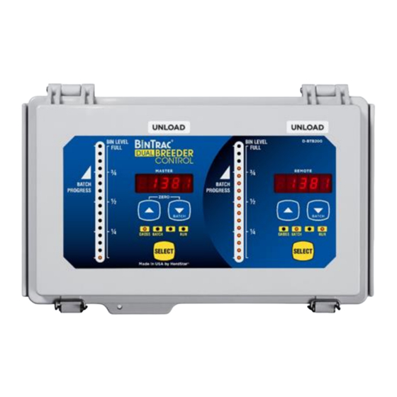
Installation Manual Configurations The BinTrac Dual Breeder Control can be used in different configurations based on your needs. Before beginning the setup of your system, determine which configuration you will be using. Below is an overview of the different configurations of batching. Included with each BinTrac Dual Breeder Control is a sheet of labels that can be used to identify the functionality of each side of the display. - Page 6 Installation Manual Weigh Bin with Triple Breeder (Load and Dual Unload Batch Method) The Single BinTrac Breeder Control and a Dual Breeder Console can be connected to a single weigh bin equipped with BinTrac load cells. The Dual Breeder Console incorporates two Breeder Controllers within a single enclosure, one Unload Control (Master) assigned to the Rooster feeding system and one Unload Control (Remote) assigned to the Hen feeding system.
-
Page 7: Installation
Installation Manual Installation Mount the Bracket Assembly 1. Remove all bolts connecting the leg to the footpad. Loosen the original anchor bolt but leave it intact at the bottom of the footpad. The footpad can and should be removed if it is binding or interfering with lifting the leg. -
Page 8: Anchor The Bin
Installation Manual Figure 4: Lift until there is a 1/2" (+/- 1/8”) gap. Figure 5: Leave 1/4” (+/- 1/8”) gap between C- channel and bracket. Repeat Steps 1 – 13 for all bin legs. After completing steps 1-13 for each leg (and before continuing to step 14), re-examine each leg to ensure proper clearances as noted and adjust as needed. -
Page 9: Wiring The Smart Summing Box
Installation Manual Wiring the Smart Summing Box In order to get a reading from the load cells, you need to tie them all together into a Smart Summing Box. One Smart Summing Box per bin is required. Refer to Addendums A through C for more in depth wiring illustrations. 18. -
Page 10: Wiring The Bintrac Power Supply
Installation Manual Wiring the BinTrac Power Supply 28. The Power Supply (PS17) is intended for inside use. As the BinTrac Breeder Control is installed in an office or building walkway, the Power Supply can be installed in the same area near an outlet. 29. -
Page 11: Wiring A Bintrac Indicator As A Remote Display
Installation Manual Wiring a BinTrac Indicator as a Remote Display A Remote Display is a BinTrac Indicator (BT200 / BT260) programmed as a Remote Display which displays the same weight data as the local BinTrac Dual Breeder Control. The Remote Display receives all of its settings (except for enabled bins) from the BinTrac Dual Breeder Control. -
Page 12: Addendum A - Unload Relay Wiring Diagram
Installation Manual Addendum A – Dual Unload Relay Wiring Diagram Below is a reference diagram for wiring up the Dual Breeder Control for a Dual Unload Batch Method. Please reference BinTrac Part # KIT-000028 Item # Part Number Part Description REL-000017 RELAY GEN PURPOSE DPDT 10A 125V (K1) CON-000126... -
Page 13: Addendum B - Load Relay Wiring Diagram
Installation Manual Addendum B – Unload/Load Relay Wiring Diagram Below is a reference diagram for wiring up the Dual Breeder Control for a Unload/Load Batch Method. Please reference BinTrac Part # KIT-000028 Item # Part Number Part Description REL-000017 RELAY GEN PURPOSE DPDT 10A 125V (K1) CON-000126 SOCKET RELAY 8 OCTAL DIN RAIL ASY-000213... -
Page 14: Addendum C - Complete Wiring Diagrams
Installation Manual Addendum C - Complete Wiring Diagrams Version 1.0 Part Number MAN-000014... - Page 15 Installation Manual Version 1.1 Part Number MAN-000014...
- Page 16 Installation Manual Version 1.1 Part Number MAN-000014...
-
Page 17: Herdstar Bintrac Product Warranty
HerdStar, LLC, although such parts may be covered by separate warranties of the respective manufacturers. This warranty set forth above does not apply if all components of a system are not supplied by HerdStar, LLC or if the goods are not purchased from and installed by an authorized distributor or company warehouse, or installed and operated in accordance with HerdStar, LLC’s specifications and instructions. -
Page 18: Bintrac Breeder Control Startup And Warranty Validation Checklist
Installation Manual BinTrac Breeder Control Startup and Warranty Validation Checklist A-Frame Bracket Inspection Checklist – Reference figures below ☐ ☐ Proper C-Channel clearance – Figure 1 ☐ ☐ Bin leg properly lifted off the concrete pad – Figure 2 ☐ ☐... - Page 19 If “No” is checked for any of these items, please consult your dealer as it may affect the performance and warranty on this system. Site Name and Location ______________________________________________________________ Inspected by _______________________________________________________________________ Date _____/_____/_____ Please fill out and return a copy to: BinTrac by HerdStar 1400 Madison Ave Suite 504 Mankato, MN 56001 Phone - 507-344-8805 Fax – 507-344-8009 Email –...
Need help?
Do you have a question about the BinTrac DBTB-200 and is the answer not in the manual?
Questions and answers