Table of Contents
Advertisement
Quick Links
FLXR4 Server and Client Radio Installation
Procedure Quick Guide
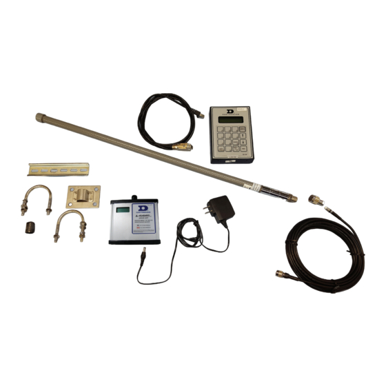
Server Radio Kit
Letter Component Type
A
Pole-Mount Hardware
B
Wall Pack Transformer
C
Antenna Extension Cable - 50'
D
DIN Rail Mount/Track
E
900Mhz Server Radio
F
Antenna Adapter
G
High Gain Antenna
Server to DM-100
H
Interconnect Cable - 10'
I
DM-100 (Existing)
Indoor Server Radio Installation
1. Mount the 900Mhz Server Radio (E) and wall pack transformer (B).
2. Feed Interconnect cable (H) between Server Radio (E) and DM-100 (I).
Warning: Applying Power to the radio without an attached antenna may cause damage!
H
Figure 2: DM-100 Interconnect
Cable
Exterior Server Radio Antenna Mounting
1. Mount High Gain Antenna (G) using mounting hardware (A) on the
outside of the building housing the server radio. Mount the antenna
as high as possible in free air. Locate the antenna within 50 feet of
the server radio location. Refer to Figure 4.
There are two antenna mounting options:
•
U bolts for pole mounting
•
Brackets for wall mounting
2. Interconnect the antenna extension cable (C) between the antenna
(G) and server radio (E).
DD4601945
Rev 01
14 May 2021
G
D
A
Figure 1: Server Kit Components
From
DM-100
Figure 3: Server Radio Connections
201 Daktronics Drive
Brookings, SD 57006-5128
www.daktronics.com/support
800.325.8766
Page 1 of 8
H
I
E
B
Figure 4: Mounted Antenna
F
C
To Wall
Pack
Advertisement
Table of Contents

Subscribe to Our Youtube Channel
Related Manuals for Daktronics FLXR4


Summary of Contents for Daktronics FLXR4
- Page 1 FLXR4 Server and Client Radio Installation Procedure Quick Guide Page 1 of 8 Server Radio Kit Letter Component Type Pole-Mount Hardware Wall Pack Transformer Antenna Extension Cable - 50' DIN Rail Mount/Track 900Mhz Server Radio Antenna Adapter High Gain Antenna...
- Page 2 Warning: Applying Power to the radio without an attached antenna may cause damage! 4. Install the power adapter harness W-4582582 that was shipped with the FLXR4 Client Radio. Refer to Figure 10. DD4601945...
- Page 3 FLXR4 Server and Client Radio Installation Procedure Quick Guide Page 3 of 8 Client Radio Set Up By default, each client defaults to SU#1 and the Network number defaults to a unique ID. Configure each client radio in sequence by completing the following steps: 1.
- Page 4 FLXR4 Server and Client Radio Installation Procedure Quick Guide Page 4 of 8 9. While the radio reboots, use the following table to note the IP address (Figure 13), radio ID number (Figure 14), and subscriber unit number (Figure 15) for each client which is unique to each site.
- Page 5 FLXR4 Server and Client Radio Installation Procedure Quick Guide Page 5 of 8 manual price updates. Quality of Service The percentage of data received by each client radio is shown in the Quality of Service area. 1. Verify that the quality of service of each client radio goes to 100.
- Page 6 FLXR4 Server and Client Radio Installation Procedure Quick Guide Page 6 of 8 RSSI Values Signal Strength <-76dBm Signal Poor–Check antennas, antenna cables, locations, height off ground, obstacles, etc. Verify Connections 1. Verify that the number of connected clients shown on the LCD is correct.
- Page 7 FLXR4 Server and Client Radio Installation Procedure Quick Guide Page 7 of 8 LCD Screen RADIOS DETECTED... INITIALIZING DISPLAYS... STARTING DISPLAY ADDRESSING... STARTING TRANSFER... PROCESSING FILE... PARSING FILE RESULTS... X NETWORKS FOUND NETWORK X OF X DETECTING DISPLAYS... DETECTED SIGN X...
- Page 8 FLXR4 Server and Client Radio Installation Procedure Quick Guide Page 8 of 8 FCC Compliance • FCC ID: R4N-AW900G2LP • IC ID: 5303A-AW900G2LP This device complies with Part 15 of the FCC Rules. Operation is subject to the following two conditions: 1.
Need help?
Do you have a question about the FLXR4 and is the answer not in the manual?
Questions and answers