
Related Manuals for Messotron MBI 46.31 Series


Summary of Contents for Messotron MBI 46.31 Series
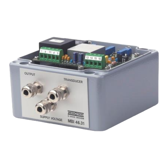
- Page 1 MBI 46.31 In field housing MBI 46.31 Eurocard PCB with front panel Operating Instructions CF Measuring Amplifier Series MBI 46.31 Version 2.1 en MBI 46.31 operating instruction.docx Issue date: 01/2022 Page 1 of 42...
-
Page 2: Table Of Contents
Contents 1 General ....................3 1.1 Warranty and liability ................ 3 1.2 Technical support and contact details ..........3 2 Safety Instructions ................4 2.1 Intended use ..................4 2.2 Conditions at the installation site ............4 2.3 General hazards if the safety instructions are not followed ....4 2.4 Qualified personnel ................ -
Page 3: General
1.1 Warranty and liability Warranty and liability claims against MESSOTRON cannot be raised if • damage occurs because the operating instructions are not followed or • modifications have been made that are not documented in the operating instructions. -
Page 4: Safety Instructions
The limits for the device are specified in chapter 11 “Technical Specifications”. Have the device checked by MESSOTRON before putting it back into service if foreign objects or liquids got inside the device. Do not use the device near other devices, machines or equipment that generate strong electric or magnetic fields. -
Page 5: Check For Transport Damage
In this case, have the device checked by MESSOTRON before use. 3 Warning and Other Messages 3.1 Use of warning messages... -
Page 6: Product Description
In this these instructions the term “displacement sensor” often Displacement abbreviated to “sensor” is used. These devices are also sensor known as “transducers” or “position sensors”. MESSOTRON differentiates the following three displacement sensor types: Differential Differential transformers consist of a primary coil and two transformer secondary coils placed around a movable magnetic core. - Page 7 Term Definition current equivalent circuit. A movable measuring tube (made of a principle conductive material) changes impedance measuring coil based on the eddy current principle. Construction Symmetric The measuring coil halves of differential transformers and sensor inductors are built in a symmetrically (mirrored) design. The electrical zero is at the center of the nominal stroke.
- Page 8 This phase shift lowers the (effective) sensitivity of the sensor in the measuring chain. All MESSOTRON series MBI 46.3x measuring amplifiers can compensate a phase shift. Linearity error...
-
Page 9: Function And Design
Signal output of the measuring amplifier (Nominal) The (nominal) output range of the measuring amplifier output range indicates the range covered by the output signal, if the displacement sensor operates in the (nominal) measuring range. Current output Analog current output of the measuring amplifier: typically 4...20 mA for the nominal stroke Voltage output Analog voltage output of the measuring amplifier:... - Page 10 P Ph ±10 V 0 ... 10 V ° Option Filter 4 ... 20 mA ° Oscillator MBI 46.10 Option Option ° high 230 V~ 15 V 24 V Figure 1 Block diagram with terminal assignment Trimmer potentiometer for gain adjustment Trimmer potentiometer for zero adjustment Trimmer potentiometer for phase compensation Resistor for setting the trim range for the zero point...
-
Page 11: Suitable Displacement Sensors
• Excitation voltage and • Rated output / sensitivity. The following chapters describe the electrical design of the three displacement sensor types offered by MESSOTRON. 4.3.1 Linear Variable Inductance Transducers (LVITs) Electrically displacement sensors based on the differential inductor principle, also called LVITs, represent a Wheatstone half-bridge consisting of two measuring coils. - Page 12 If the core is moved out of its mid-position, the impedances of the two measuring coils change and the measurement voltage increases proportionally with the displacement within the measuring range. 4.3.2 Linear Variable Differential Transformers (LVDTs) Differential transformers consist of a primary coil and two secondary coils placed around an immersion core.
- Page 13 4.3.3 Long-stroke sensor (eddy current principle) Long-stroke sensors are displacement sensors using a half-bridge circuit. Only one coil is used as the measuring coil. The second coil is designed as a space- saving equivalent circuit. A movable measuring tube (made of a conductive material) changes the impedance of the measuring coil based on the eddy current principle.
-
Page 14: Overview Of Types And Options
4.4 Overview of types and options MBI 46.31. x y /zzz Power Version and output signal Options supply /nn kHz – alter- ±15 VDC 1 1 Eurocard PCB without front panel, ±10 V output; connector native CF in the range 1...20 kHz 230 VAC 2 2 Eurocard PCB without front panel, /0-10 V output... - Page 15 4.4.1 Eurocard PCB + 15 V -15 V Option (Option) 24 V high 24 V low MBI 46.10 Weight app. 0,1 kg Figure 6 Enclosure dimensions and position of components for Eurocard PCBs CF measuring amplifiers in the Eurocard PCB format are intended for mounting into subracks (3 U) or other suitable housings.
- Page 16 NOTICE All unused cable passages must be closed using suitable sealing plugs for protection against moisture and dirt. Connections for power supply, output signal and displacement sensors are routed to the outside using three M12 cable glands (maximum cable diameter 6.5 mm).
- Page 17 Field enclosure with 230 VAC supply + 15 V -15 V Option) Option MBI 46.10 Weight app. 2 kg Figure 8 Enclosure dimensions and position of components for 230 VAC supply. The power supply unit is located on a separate power supply board, mounted to the back of the main board.
-
Page 18: Placing Into Service
5 Placing into Service NOTICE NOTICE Only qualified skilled persons are allowed to place the measuring amplifier into service. NOTICE Electrostatic discharge at electronic assemblies can damage the components before they are placed into service. Therefore, take all necessary measures to avoid electrostatic charging (ESD protective measures). - Page 19 WARNING Hazardous voltages inside the measuring amplifier with 230 V supply voltage (type 46.31.2x). Touching live parts can result in death, serious injury or considerable property damage. • Before opening the field enclosure, check all conductors. They must be de- energized.
-
Page 20: Setting Options Of The Measuring Amplifier
8 4 (D) WH+YE 1 (A) Figure 12 Connection of MESSOTRON displacement sensors 5.2 Setting options of the measuring amplifier The measuring amplifier must be adapted to the (displacement) sensor used. The following parameters must be set: • Position of the electrical zero point, •... - Page 21 • the sensor that may have been ordered at MESSOTRON together with the amplifier or • a typical adjustment, if the sensor is unknown. The basic configuration can be changed, if required (see chapter 5.4 Basic configuration of measuring amplifier), for instance if a different sensor is used or if the output range of the measuring amplifier is changed ((such as from 0 V...10 V to ±10 V).
- Page 22 If a more significant shift of the electrical zero point is required (e.g. to the start or to the end of the measuring range), the basic setting must be changed. This can only be accomplished by changing fixed resistors (refer to chapter 5.4.3). 5.2.2 Phase compensation Due to the design principle, inductive displacement sensors can show a phase shift between the excitation voltage and the measurement voltage.
-
Page 23: Adjustment Using Trimming Potentiometer
output signal does not reach the desired value, e.g. at the end of the nominal stroke, the gain must be increased. Uout desired Uout actual Displacement Figure 15 Gain correction A larger gain causes an increase in the gradient of the displacement-to-output- signal characteristic curve (or a counter-clockwise rotation of the characteristic curve). - Page 24 WARNING Hazardous voltages inside the measuring amplifier with 230 V supply voltage (type 46.31.2x). Touching live parts can result in death, serious injury or considerable property damage. • Only qualified skilled persons are permitted to adjust the measuring amplifier. The measuring amplifier will only show its nominal characteristics NOTE after a warm-up time of approximately 15 minutes.
- Page 25 Other output ranges, e.g. 0...10 V, require a zero offset NOTE according to chapter 5.4.3. • To adjust the zero point, remove the core from the sensor housing and set the output signal of the measuring amplifier to 0 V or 12 mA using the zero- point potentiometer P .
-
Page 26: Basic Configuration Of Measuring Amplifier
In this case, send the measuring amplifier freight prepaid along with your requirements (measurement range, desired output range) to MESSOTRON. If you are using a third-party sensor, we also need the displacement sensor or at least its specifications. - Page 27 5.4.1 Location of fixed resistors and capacitors The location of the components that may have to be replaced is shown in the following figure: Capacitors C and C Resistors R and R for zero offset phase adjustment Resistor R for basic setting of gain Capacitor C for noise rejection...
- Page 28 • If the output signal decreases, then connect the decade box instead of C and look for the maximum of the output signal there. • For C and/or C solder in a capacitor which is approx. 10...20 % larger than the value you have determined.
- Page 29 The required resistance values for the offset depend, among NOTE other things, on the adjusted amplification of the measuring amplifier. It is advisable that you use a resistance decade box to dimension the resistors. Connect it to the soldering terminals of the resistance to be determined NOTICE NOTICE...
- Page 30 Displacement sensors with known rated output: First check the position of jumper JU1. It provides a 6x pre- NOTE amplification of the measurement voltage. • If the rated output (determined independently of the phase) of the sensor is 60 mV/V or more then the preamplifier can be switched off (jumper JU1 in plug position J •...
- Page 31 Displacement sensor with unknown rated output, changing the output range or reduced measuring range: In these special cases, the fixed resistor R cannot be determined using Figure 20. It must be determined by experiment. • First switch off the preamplifier (jumper JU1 in plug position J •...
-
Page 32: Optimizing The Linearity Characteristic Of The Measuring Chain
5.5 Optimizing the linearity characteristic of the measuring chain The procedure for basic settings and adjustment described in the previous chapters applies to a measuring chain with an “ideal displacement sensor” without linearity deviation. Some real displacement sensors show a distinctive “one-sided” linearity deviation. - Page 33 5.5.1 Optimization with the smallest possible error in the zero point If the measuring task mainly requires a minimum error at the zero point of the displacement sensor, then the maximum deviation needs to be reduced in the measuring range. •...
- Page 34 Graph 2 Graph 3 -50 -45 -40 -35 -30 -25 -20 -15 -10 -0,1 -0,2 -0,3 Displacement in % Figure 23 Smallest deviation over the entire measurement range 5.5.3 Other linearity optimizations Graph 2 -50 -45 -40 -35 -30 -25 -20 -15 -10 -5 10 15 20 25 30 35 40 45 50 Graph 4 -0,1...
-
Page 35: Improving The Noise Rejection
To set the measuring amplifier according to these instructions, NOTE the linearity curve of the displacement sensor must be determined. As an option for all MESSOTRON displacement sensors, you can receive test reports with the linearity curve (according to 5.5.1 Optimization with the smallest possible error in the zero point). -
Page 36: Operation
Never try to repair a defective measuring amplifier. Repair attempts of any kind will immediately render warranty and liability claims invalid. MESSOTRON electronics are designed for use in a rough industrial environment. They are designed for years of trouble-free operation. -
Page 37: Maintenance
• To clean the enclosure and the front panel, only use a soft, slightly moist cloth. • Remove dry dirt from PCBs carefully using a vacuum cleaner or a brush. • If foreign liquids get inside the device, have it checked by MESSOTRON before putting it back into service. 9 Disposal The device, any accessories and the packaging must be disposed of in accordance with the respective national regulations. -
Page 38: Eu Declaration Of Conformity
10 EU Declaration of Conformity 10.1 Electronics with a supply voltage < 50 V Version 2.1 en MBI 46.31 operating instruction.docx Issue date: 01/2022 Page 38 of 42... -
Page 39: Electronics With A Supply Voltage > 50 V
10.2 Electronics with a supply voltage > 50 V Version 2.1 en MBI 46.31 operating instruction.docx Issue date: 01/2022 Page 39 of 42... -
Page 40: Technical Specifications
11 Technical Specifications General information Operating temperature 0...60 °C Storage temperature -25...85°C Electromagnetic compatibility DIN EN 61326-1 Electric safety DIN EN 61010-1 Measuring amplifier Linearity error < 0,1 % FSO Carrier frequency 5 kHz ±5 % (sine); optional 1...20 kHz Excitation voltage (primary) approx. - Page 41 Eurocard PCB Supply voltage MBI 46.31.1y: ±15 VDC stabilized MBI 46.31.3y: +20...+36 VDC Power consumption max. 2 W Electrical connection Connector to DIN 41612, 32-pin multi- point plug, type C Required mating plug 32-pin multi-point strip Special designs: 16-pin terminal block Dimensional data approx.
- Page 42 Subject to alterations. Errors and omissions excepted. © 2022, MESSOTRON Hennig GmbH & Co KG MESSOTRON GmbH & Co KG Friedrich-Ebert-Str. 37 64342 Seeheim-Jugenheim, Germany Phone: +49 6257 999 730 Email: info@messotron.de Homepage: www.messotron.com Version 2.1 en MBI 46.31 operating instruction.docx...
Need help?
Do you have a question about the MBI 46.31 Series and is the answer not in the manual?
Questions and answers