
Related Manuals for Messotron MBI 46.51.39 Series


Summary of Contents for Messotron MBI 46.51.39 Series
- Page 1 Operating Instructions MBI 46.51.39 Operating instructions for Carrier Frequency Amplifier Series MBI 46.51.39 Version 0.9 en MBI 46.51.39 operating instructions.docx Issue: 08/2022 page 1 from 29...
-
Page 2: Table Of Contents
Types and options ................11 5 Commissioning ..................13 Wiring Details / Pin Assignment ............14 Use with MESSOTRON transducers ........... 15 Setting and adjustment options ............16 Setting of transducer type ..............18 Adjustment of gain range ..............19 Adjustment of offset, gain and phase-shift........... -
Page 3: General
Please read and follow these operating instructions carefully. 1.1 Warranty and liability Any warranty and liability claim against MESSOTRON shall be lost if • damage occurs due to non-observance of the operating instructions • modifications have been made that are not documented in this manual •... -
Page 4: Safety
Before unpacking, check the packaging of the device for any damages. If the packaging has been damaged during transport and if there is a suspicion of damage to the device, it may not be put into operation. Have MESSOTRON check the device before using it. Version 0.9 en MBI 46.51.39 operating instructions.docx... -
Page 5: Warnings And Markings
Operating Instructions MBI 46.51.39 3 Warnings and markings 3.1 Use of warnings For warnings, the following hazard classes are specified according to ANSI. Z 535 used: Warning sign, signal word Meaning Indicates a dangerous situation in which death or serious DANGER bodily injury occurs if it is not avoided. -
Page 6: Product
Operating Instructions MBI 46.51.39 4 Product 4.1 Terms and definitions Term Definition Carrier frequency Carrier frequency measuring amplifiers are used for LVDT/LVIT: measuring amplifier • to provide the inductive sensor with the excitation voltage • to amplify the sensor output signal •... - Page 7 (e.g. 10 mV/V/mm). For standardization purposes information on sensitivity and rated output for MESSOTRON displacement sensors is determined and provided independent of phase (i.e. without consideration of a phase shift). Phase (phase shift) With inductive sensors and/or long connecting cables, there will be a noticeable phase shift between the excitation voltage and the measurement voltage.
-
Page 8: Function And Design
Operating Instructions MBI 46.51.39 4.2 Function and design The MBI 46.51.39 carrier frequency amplifier generates an alternating excitation voltage required for the operation of inductive displacement transducers. The carrier frequency is typically 5 kHz, unless otherwise specified. The output signal from the displacement transducer is pre-amplified by the measuring amplifier and evaluated ratiometrically, i.e. - Page 9 Operating Instructions MBI 46.51.39 The electrical design of the three displacement transducer types offered by MESSOTRON is described below. 4.3.1 Linear Variable Inductive Transducers (LVIT) Electrically, a displacement transducer based on the differential inductor principle represents a Wheatstone half-bridge consisting of two measuring coils. The core, which moves inside the coils, causes in its middle position (electrical zero point) that both measuring coils have the same impedance.
- Page 10 Operating Instructions MBI 46.51.39 Prinzipschaltbild TF- Verstärker ° ° Oszillator Tauch anker ° ° Filter Mess ° Figure 2 amplifier with differential transformer 4.3.3 Long-stroke sensors (eddy current principle) Long-stroke displacement transducers are sensor using a half-bridge circuit in which only one coil is used as a measuring coil and the second coil is designed in a space-saving replacement circuit.
-
Page 11: Types And Options
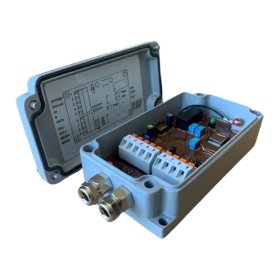
Operating Instructions MBI 46.51.39 4.4 Types and options The amplifier is available in the following versions: MBI 46.51.39 Standard 5 kHz carrier frequency 24 VDC supply voltage (0...10 V) current output (4... 20 mA) field housing terminal block Options: other carrier frequency in the range (1...20 kHz) 4.4.1 Layout / Drawing The device comes in a rugged aluminum field housing of industrial standard. - Page 12 Operating Instructions MBI 46.51.39 Cable feedthroughs that are not used shall be closed with a suitable plug for protection against moisture and dirt from outside. The individual strands of the connection cables are placed in the protected interior of the housing.
-
Page 13: Commissioning
Operating Instructions MBI 46.51.39 5 Commissioning WARNING The amplifier may only be put into operation by qualified personnel. Electrostatic discharges on electronic assemblies can lead to damage or direct failure of components. Therefore, take all necessary measures to avoid electrostatic charging (ESD protective measures). -
Page 14: Wiring Details / Pin Assignment
Operating Instructions MBI 46.51.39 5.1 Wiring Details / Pin Assignment The connection of the device / amplifier is carried out according to the assignment in the following table using spring-loaded terminals. There is no soldering work required. Pin / Clamp Type Assignment Supply... -
Page 15: Use With Messotron Transducers
Operating Instructions MBI 46.51.39 5.2 Use with MESSOTRON transducers When connecting a MESSOTRON displacement transducer according to the following table, a positive (growing) output signal results when the core is moved out of the displacement transducer, or the measuring tube is moved down / away from the transducer coil. -
Page 16: Setting And Adjustment Options
5.3.1 Position of the electric zero point The electrical output signal of a real inductive displacement transducer is not always exactly zero at mechanical zero point (with MESSOTRON displacement transducers according to dimension A ). Material and manufacturing tolerances can lead to deviations, which can be corrected with the zero point potentiometer. - Page 17 Operating Instructions MBI 46.51.39 Speisespg. Messspg. 100 120 140 160 180 200 220 240 260 280 300 320 340 360 Figure 9 Shift Figure 9 shows that without phase compensation, a reduced voltage ratio of /US results. Phase compensation results in an optimized voltage ratio /US.
-
Page 18: Setting Of Transducer Type
Operating Instructions MBI 46.51.39 Soll UA Ist Messweg Figure 10 9Correct the gain A higher gain causes a greater slope of the measuring path-output signal characteristic curve (or rotation of the characteristic curve counterclockwise). 5.4 Setting of transducer type Before starting the adjustment, the measuring amplifier must be set whether an inductive displacement transducer with symmetrical or with asymmetrical coil mount is to be used. -
Page 19: Adjustment Of Gain Range
Operating Instructions MBI 46.51.39 5.5 Adjustment of gain range To match the measuring amplifier with the sensitivity of the sensor, the gain range be selected by use of JP1 jumper. Depending on the nominal output signal of the transducer used, the plug-in bridge is plugged into one of the 4 gain ranges. - Page 20 Operating Instructions MBI 46.51.39 zero-point / offset gain adjustment phase shift compensation Figure 12 Position of the trim potentiometers Version 0.9 en MBI 46.51.39 operating instructions.docx Issue: 08/2022 page 20 from 29...
- Page 21 Operating Instructions MBI 46.51.39 5.6.1 Adjustment process for symmetrical transducers With symmetrical displacement transducers, the electrical zero point is in the middle of the nominal measuring stroke. Typically, the voltage output of the amplifier also provides a symmetrical output signal for a symmetrical displacement transducer. •...
-
Page 22: Optimization Of The Linearity Behavior
Operating Instructions MBI 46.51.39 5.7 Optimization of the linearity behavior The procedure for the basic settings and the adjustments described in the previous chapters apply to a measuring with an "ideal displacement transducer" without linearity deviation. However, real displacement transducers have a linearity deviation. In these cases, the linearity behavior of the transducer can be further optimized taking into account the respective measuring task. - Page 23 Operating Instructions MBI 46.51.39 Kurve -50 -45 -40 -35 -30 -25 -20 -15 -10 -0,1 -0,2 -0,3 -0,4 Messweg in % Figure 14 Ideal zero-point linearity, max linearity error reduced to 0.32% 5.7.2 Optimization with minimal absolute error If the linearity curve shall be optimized for minimal overall absolute error diregarding the zero- point accuracy, then you can further improve the curve omitting the setting at zero point.
- Page 24 Operating Instructions MBI 46.51.39 5.7.3 Other linearity optimizations Kurve 2 -50 -45 -40 -35 -30 -25 -20 -15 -10 -5 10 15 20 25 30 35 40 45 50 Kurve 4 -0,1 -0,2 -0,3 -0,4 -0,5 Messweg in % Figure 1613 Null error setting at the beginning and end of the measuring range Version 0.9 en MBI 46.51.39 operating instructions.docx...
-
Page 25: Operation
The device is intended for unattended continuous operation. WARNING For decommissioning, it must be disconnected from the power supply. If foreign objects or liquids enter the device, have the device checked by MESSOTRON before using it again. 7 Repair HINT Do not try to repair a defective amplifier independently. -
Page 26: Maintenance
• Clean the case or front panel only with a soft, slightly damp cloth. • Carefully remove dry dirt on the boards with a dust cleaner or brush. • If liquid gets into the device, have the device checked by MESSOTRON before using it again. -
Page 27: Eu Declaration Of Conformity
Operating Instructions MBI 46.51.39 10 EU Declaration of Conformity 11 Specifications Version 0.9 en MBI 46.51.39 operating instructions.docx Issue: 08/2022 page 27 from 29... - Page 28 Operating Instructions MBI 46.51.39 MBI 46.51.39 Measuring amplifier for operation of inductive displacement sensors Linearity error < 0,1 % FSO 5 kHz ±5 % Carrier frequency optional 1...20 kHz Dynamic bandwidth 500 Hz (3 dB, at 5 kHz) Excitation voltage approx.
- Page 29 Operating Instructions MBI 46.51.39 Changes and errors excepted. © 2022, MESSOTRON GmbH & Co KG MESSOTRON GmbH & Co KG Friedrich-Ebert-Str. 37 D-64342 Seeheim-Jugenheim Germany Tel: +49 6257 999 730 Fax: +49 6257 999 7309 Email: info@messotron.com Web: www.messotron.com Version 0.9 en MBI 46.51.39 operating instructions.docx...
Need help?
Do you have a question about the MBI 46.51.39 Series and is the answer not in the manual?
Questions and answers