Advertisement
Quick Links
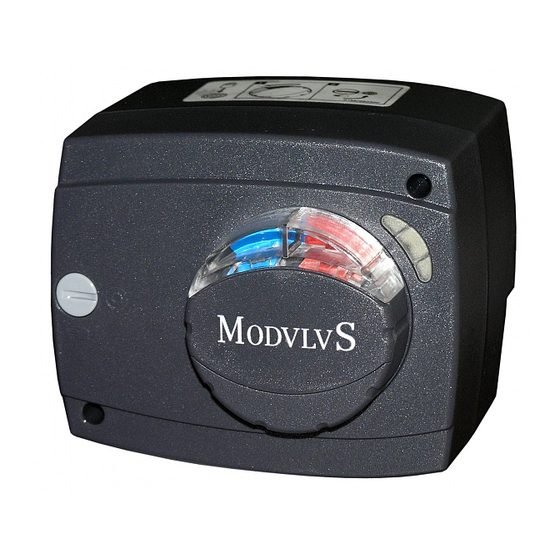
Actuator
For Mixing Valve
For the connection of the actuator to the electric power supply, a circuit breaker with an open contact gap
of at least 3 mm shall be implemented for each of the line conductors.
Prior to starting to connect the actuator, please check whether the mains power supply, or the main circuit
breaker, has been turned off.
Mounting Instructions
1. *Take the button, lever or indicator (depending on the
actuator model) off, remove the scale and loosen the
screws. Remove the actuator cover (cf. Picture 1), too.
2. *Insert the electrical supply cable through the cable gland
and connect the electrical conductors (cf. Fig. 2-I). Fasten
the cables (cf. Fig. 2-II) and adjust the ring (depending
on the actuator model) for the additional switch (cf. Fig. 2-III).
3. *Return the motor cover to its original position and fasten
both screws (cf. Fig. 3).
4. Put the adapter "b" onto the motor shaft "a" and turn it to the
centre of the valve scale. Fasten the locking screw "c" to the
valve. Position the actuator "d" onto the adapter "b".
The possible actuator mounting positions are indicated in
Figure 4-I.
As per factory default, the actuator is set to the central
position (45 Đ°).
Insert the scale "f"; while adjusting it, pay attention to the
open and closed positions of the valve. Finally, insert the
button "h", handle "g", or indicator "i", ensuring that the
position of the accessory applied complies with the scale.
Insert and fasten the screw "l". Cover the button with the lid
"j" or "k".
* Valid for actuators supplied without cable.
Instructions For Use
Automatic operation
When the button "e" (Fig. 4) is in the position
, the
actuator, operates automatically.
Manual operation
When the button "e" (Fig. 4) is in the position
the actuator
operation is turned off.
The valve position can be set manually by the button or handle.
Indication Lamps
The actuator has 3 indication lamps. The left and right lamps
indicate the actuator rotation direction (Fig. 2-III). The central
lamp indicates the state of the additional switch (depending on
the actuator model).
Orange (rotation to left)
Red (switch AUX is ON))
Orange (rotation to right)
3 point / 3 point+SWITCH
N L
230 V (24 V) ~
SWITCH
1
2
3
4
5
1 2 3
4 5 6
M21
MP21
N
M21-AUX
M41
Proportional
S1
S2
SIG.
S3
U/I
0
0
U
0
0-10 V / 0-20 mA
2-10 V / 4-20 mA
1
1
I
1
S4
0
1
S5 S6
0
0
60s
AC 24 V
0
1
90s
DC 24 V
1
0
120s
1
1
120s
Y DC 0 (2)...10 V
U DC 0 (2)...10 V
1
2
3
4
1 2 3
4 5 6
1
M51
Y
U
a
c
b
d
ASCAVMSA
Esbe, Seltron, Somatherm, Acaso, IVAR, PAW, Hora,
BRV, IMIT, Barberi, Olymp, Hoval (5 Nm)
3
ASCAVMSB
Esbe, Seltron, Somatherm, Acaso, IVAR, PAW, Hora,
BRV, IMIT, Barberi, Olymp, Hoval (10 Nm, 15 Nm)
Technical data
M21, MP21, M21-AUX, M41
Maximum load
5 Nm
Rotation angle
90 °
Running time
2 min
Supply voltage
230 (24) V ~, 50 Hz
Consumption
2,5 VA
Protection degree
IP42
Protection class
II
Dimensions (WxHxD)
84 x 101 x 85 (72)
Weight
460 g
Disposal of Old Electrical & Electronic
Equipment
(Applicable in the European Union and other European
countries with separate collection systems)
This symbol on the product or on its packaging
indicates that this product shall not be treated as
household waste. Instead it shall be handed over to
the applicable collection point for the recycling of
electrical and electronic equipment.
By ensuring this product is disposed of correctly, you will help
prevent potential negative consequences for the environment
and human health, which could otherwise be caused by
inappropriate waste handling of this product.
The recycling of materials will help to conserve natural
resources. For more detailed information about recycling of this
product, please contact your local city office, your household
waste disposal service or the shop where you purchased the
product.
AUX - SWITCH
ENG
4 5 6
4 5 6
2-III
2-I
c
e
g
k
ENG
Mischerstellmotor
Beim Anschluß des Stellmotors an das Stromnetz muß zur Netztrennung für jeden Phasenleiter eine
Trennvorrichtung mit einem Luftspalt von mindestens 3 mm zwischen offenen Kontakten eingesetzt werden.
Eher der elektrische Anschluß des Stellmotors unternommen wird, soll unbedingt überprüft werden, ob die
Stromversorgung bzw. die Hauptsicherung abgeschaltet wurde.
Montageanleitung
1. * Drehknopf, Hebel oder Indikator (je nach Ausführung des
M51-05
Stellmotors) abnehmen, Skala beseitigen und beide
Schrauben herausdrehen. Auch Abdeckung des Stellmotors
60 / 90 / 120 s
abbauen (Abb. 1).
24 V AC/DC
2. * Stromkabel durch die Durchführung einführen und Leiter
5 VA
anschließen (Abb. 2-I). Kabelzugentlastung befestigen
(Abb. 2-II) und Ring für Zusatzschalter AUX (je nach
Stellmotormodell) einstellen (Abb. 2-III).
3.* Stellmotorabdeckung wieder aufsetzen und beide
Schrauben anziehen (Abb. 3).
4. Adapter "b" auf die Motorwelle "a" aufsetzen und zur
Skalenmitte des Mischers drehen. Sperrschraube "c" am
Mischer befestigen. Stellmotor "d" auf Adapter "b"
aufsetzen. Die möglichen Montagepositionen sind in
Abb. 4-I dargestellt.
Werksseitig ist der Stellmotor in die mittlere Stellung (45 Đ °)
eingestellt.
Jetzt Skala "f" einsetzen - während der Skaleneinstellung die
Mischerpositionen "offen" und "geschlossen" beachten.
Zum Schluß Drehknopf "h", Hebel "g" oder Indikator "i"
aufsetzen, dabei unbedingt darauf achten, daß die
Drehknopfstellung mit der Skala bereinstimmt. Schraube "l"
einsetzen und festziehen. Drehknopf mit Abdeckung "j" bzw.
Indikator mit Abdeckung "k" abdecken.
* Gültig für ohne Kabel gelieferten Stellmotoren.
Gebrauchsanweisung
Automatikbetrieb
Wenn der Drehknopf "e" (Abb. 4) sich in der Stellung
befindet, fuktioniert der Stellmotor selbsttätig.
Handbetrieb
Wenn der Drehknopf "e" (Abb. 4) sich in der Stellung
befindet, ist der Stellmotorbetrieb ausgeschaltet.
Die Mischerposition kann manuell mittels Drehknopf oder Hebel
eingestellt werden.
Anzeigelämpchen
Der Stellmotor hat 3 Anzeigelämpchen. Das linke und rechte
Lämpchen zeigen die Drehrichtung des Stellmotors an (Abb. 2-
III). Das mittlere Lämpchen zeigt den Zustand des zusätzlichen
Schalters AUX an (je nach Stellmotormodell).
DEU
FRE
ITA
SPA
M21, MP21, M21-AUX, M41, M51-05
i
f
h
k
k
4-I
j
Technische Daten
Maximale Belastung
Drehwinkel
Laufzeit
Nennspannung
Nennleistung
Schutzart
Schutzklasse
Abmessungen (BxHxT)
Masse
Entsorgung von gebrauchten elektrischen und
elektronischen Geräten
(anzuwenden in den Ländern der Europäischen Union und
anderen europäischen Ländern mit einem getrennten
Sammelsystem für diese Geräte)
Das Symbol auf dem Produkt oder seiner
Verpackung weist darauf hin, dass dieses Produkt
nicht als normaler Haushaltsabfall zu behandeln
ist, sondern an einer Annahmestelle für das
Recycling von elektrischen und elektronischen Geräten
abgegeben werden muss. Durch Ihren Beitrag zum korrekten
Entsorgen dieses Produkts schützen Sie die Umwelt und die
Gesundheit Ihrer Mitmenschen. Umwelt und Gesundheit werden
durch falsches Entsorgen gefährdet. Materialrecycling hilft den
Verbrauch von Rohstoffen zu verringern. Weitere Informationen
über das Recycling dieses Produkts erhalten Sie von Ihrer
Gemeinde, den kommunalen Entsorgungsbetrieben, oder dem
Geschäft, in dem Sie das Produkt gekauft haben.
,
Orange (rotation links)
Rot (Schalter AUX is EIN)
Orange (rotation rechts)
~
GRE
0 1 MC0 6 0 4 4 0
max. 22-18 AWG
2
max. 1.5 mm
2-II
2
M3060062
4
DEU
M21, MP21, M21-AUX, M41
M51-05
5 Nm
90 °
2 min
60 / 90 / 120 s
230 (24) V ~, 50 Hz
24 V AC/DC
2,5 VA
5 VA
IP42
II
84 x 101 x 85 (72)
460 g
Advertisement

Related Manuals for BRV ModvlvS M21

Summary of Contents for BRV ModvlvS M21
- Page 1 Esbe, Seltron, Somatherm, Acaso, IVAR, PAW, Hora, BRV, IMIT, Barberi, Olymp, Hoval (5 Nm) ASCAVMSB Esbe, Seltron, Somatherm, Acaso, IVAR, PAW, Hora, BRV, IMIT, Barberi, Olymp, Hoval (10 Nm, 15 Nm) Actuator For Mixing Valve Mischerstellmotor For the connection of the actuator to the electric power supply, a circuit breaker with an open contact gap Beim Anschluß...
- Page 2 Servomoteur de vanne Servomotore per valvole miscelatrici Lors du branchement du moteur ŕ l'alimentation du réseau électrique, pour tous les conducteurs de phase, Per il collegamento del motore alla rete di alimentazione č necessario adoperare, per tutti i conduttori di il faut utiliser un dispositif de contact dont l'écart entre les contacts ouverts est de 3 mm minimum.
Need help?
Do you have a question about the ModvlvS M21 and is the answer not in the manual?
Questions and answers