
Subscribe to Our Youtube Channel
Related Manuals for BRV ModvlvS Logico

Summary of Contents for BRV ModvlvS Logico
- Page 1 Heating Controller ModvlvS Logico Weather-compensated heating circuit controller Installation and operating instructions Read carefully before installation, commissioning and operation...
-
Page 2: Table Of Contents
DHW reference Changes to the Unit DHW comfort Warranty and Liability DHW hysteresis Disposal and Pollutants Buffer DHW load DHW priority Description ModvlvS Logico PV contact About the Controller 14-day Reference Specifications Burner Scope of supply DHW request Hydraulic Variants... -
Page 3: Safety Instructions
Safety Instructions EU-Conformity By affixing the CE mark to the unit the manufacturer declares that the ModvlvS Logico conforms to the following relevant safety regulations: EU low voltage directive 2014/35/EU EU electromagnetic compatibility directive 2014/30/EU conforms. Conformity has been verified and the corresponding documentation and the EU declaration of conformity are kept on file by the manufacturer. -
Page 4: Changes To The Unit
In the menu 'measurement values and settings' are help text and graphics in addition to key words. The ModvlvS Logico can be used with different variants of installations, see " Hydraulic Variants " on page 6see “hydraulic vari- ants”... -
Page 5: Specifications
Specifications Electrical specifications: Power supply 100 - 240VAC, 50 - 60 Hz Power consumption / standby 0.5 - 2.5 W/ 0.5 Total switched power Switched power per relay Internal fuse 2 A slow 250V Protection category IP40 Protection class / overvoltage category II / II Inputs/Outputs Sensor inputs... -
Page 6: Scope Of Supply
3 screws 3,5 x 35 mm and 3 plugs 6 mm for wall installation. 6 strain relief clips with 12 screws, replacement fuse 2TA ModvlvS Logico Installation and operating instructions Optionally contained depending on design/order: External relay for V1 / V2: 0-10V relay 1W / 6A (77502) -
Page 7: Installation
Installation Electrical Terminals Low voltage Mains voltages max. 24 VAC / DC 230 VAC 50 - 60 Hz On the control board VFS1 Grundfos Direct Sensor VFS2 Grundfos Direct Sensor CAN bus connection (1=high,2=low) CAN bus connection (1=high,2=low) Terminal: Connection for: Terminal: Connection for: GND bridge on the lower ground terminal block... -
Page 8: Wall Installation
Wall Installation 1. Unscrew cover screw completely. 2. Carefully pull upper part of housing from lower part. During the removal, the brackets are released as well. 3. Set upper part of housing aside Do not touch the electronics. 4. Hold the lower part of the housing up to the selected position and mark the three mounting holes. -
Page 9: Electrical Connection
Electrical Connection Before working on the unit, switch off the power supply and secure it against being switched on again! Check that there is no power flowing! Electrical connections may only be made by a specialist and in compliance with the applicable regulations. -
Page 10: Operation
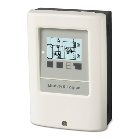
Operation Display and Input The display‘s (1), extensive text and graphical mode, enables simple, almost self-explanatory, operation of the con- troller. The LED (2) lights up green when a relay is switched on. The LED (2) lights up red when operating mode ‚Off‘ is set. The LED (2) flashes quickly red when an error is present. -
Page 11: Commissioning Help
Commissioning help 1. Set language and time 2. Commissioning help / setup wizard a) select or b) skip. The setup wizard guides through the necessary basic settings in the cor- rect order. Each parameter is explained in the control display. Pressing the „esc“ key takes you back to the previous setting. b) With free commissioning the settings should be made in the following order: menu 10. -
Page 12: Statistics
2. Statistics Serve for function control and long-term monitoring of the system. For system data statistics it is essential for the time to be set accurately on the controller. Please note that the clock con- tinues to run for about 24 hours if the mains voltage is inter- rupted, and afterward must be reset. -
Page 13: Times
3. Times Settings for time, date and operating times for the heating circuit. The associated temperature reference values are specified in Menu 5, ‚Settings‘. Time & Date Serve to set the current time and date. For system data statistics it is essential for the time to be set accurately on the controller. Please note that the clock continues to run for about 24 hours if the mains voltage is interrupted, and afterward must be reset. -
Page 14: Operating Mode
4. Operating mode Manual In ‚Manual‘ mode, the individual relay outputs and the connected consumers can be checked for proper functioning and correct assignment. The operating mode ‚Manual‘ may only be used by specialists for brief function tests, e.g. during commissioning! Func- tion in manual mode: The relays and thus the connected consumers are switched on and off by pressing a key, with no regard to the current temperatures and set parameters. -
Page 15: Day Correction
The characteristic curve is used to control the heat dissipation of the heating circuit relative to the outdoor temperature. The demand for heat differs due to factors such as the type of building, heating, insulation and outdoor temperature. For this reason, the controller can operate with a normal straight curve (setting ‚simple‘) or split curve (setting ‚split‘). -
Page 16: Reference/Actual
Heat request is started when the flow temperature is continuously below reference temperature for 1 minute. Reference/Actual + This value determines the acceptable underflow of the heating circuit temperature beyond the calculated reference flow tem- perature at the buffer sensor or flow sensor. If the temperature at the buffer sensor exceeds the reference flow temperature by the value set here, the heating request is deactivated. -
Page 17: Mixer Run Time
Mixer off factor The calculated pause time of the mixer is multiplied with the value set here. If the pause factor is ‚1‘, the normal pause time is used, ‚0.5‘ will use half the normal pause time. Setting the pause factor to ‚4‘ would quadruple the pause time. Mixer increase If the temperature rises very fast, this value is added to the measured flow temperature so that the mixer’s reaction is stronger. -
Page 18: Dhw Hysteresis
Switching: Request is made via signal output V2. Output signal to V1: "no request" = 0V, "request" = 10V Modulating: Request is made via signal output V2. The ModvlvS Logico outputs the requested temperature (calculated target VL) as a voltage via the signal output. -
Page 19: Burner Offset
Example: Calculated target VL heating circuit 43 ° C, measured VL at sensor S2 40 ° C. If the VL sensor exceeds the setpoint VL by 2K (preferece/actual -) for more than 2 minutes, the ModvlvS Logico requests a heat source with 4.3V (corresponds to 43 °... -
Page 20: Protective Functions
6. Protective Functions The 'Protective functions‘ can be used by specialists to activate and set vari- ous protective functions. By no means does the controller replace the safety appliances on site! Seizing Protection If the anti-seizing protection is activated, the controller switches the heat pump and the mixer on/off at 12:00 noon for 5 seconds to prevent seizing of the pump/valve after long periods of inactivity. -
Page 21: Special Functions
7. Special Functions Used to set basic items and expanded functions. The settings in this menu should only be changed by a specialist. Program selection Here the hydraulic variation fitting to the respective use case is selected and set. The program selection normally occurs only once during the first entry into service by a specialist. An incorrect pro- gram selection may lead to unpredictable errors. -
Page 22: Ethernet
You can find the address of the connector or respectively the data logger on the address sticker on the outside of the casing. Pointers and help on how to establish a connection you can find in the enclosed SOREL connect instructions or the instructions of the data logger. -
Page 23: Menu Lock
8. Menu Lock Secure the controller against unintentional changing and compromise of basic functions. The menus listed below remain completely accessible despite the menu lock being activated, and can be used to make adjustments if necessary: 1. Measurement values 2. Statistics 3. -
Page 24: Malfunctions/Maintenance
Malfunctions/Maintenance Replacing the Fuse Repairs and maintenance may only be performed by a specialist. Before working on the unit, switch off the power sup- ply and secure it against being switched on again! Check that there is no power flowing! Only use the supplied spare fuse or a fuse of the same design with the following specifications: 2 AT/250 V If the mains voltage is switched on and the controller still does not function or dis- play anything, then the internal device fuse may be defective. -
Page 25: Additional Information
Additional Information CAN bus The CAN bus can be used to connect two or more controllers with each other or with the data logger to exchange data. 1. The controllers are connected in series with the CAN bus cable. 2. The first and last controllers in this connection in series must be fitted with terminating resistance. -
Page 26: Appendix
Appendix Pump In this menu, the preset profiles for the pump can be selected or under “manual” all settings can be done personally. The settings can still be changed after a profile has been selected. Profile Delete this text and replace it with your own. Output Signal In this menu, the type of pump is set: heating pumps have the greatest output with a small input signal, solar pumps in contrast have very little output with a small input signal. -
Page 27: Technical Data Pwm And 0-10V
Technical data PWM and 0-10V Show signal Represents the set pump signal in a graphic and text overview. - Page 28 Final declaration Although these instructions have been created with the greatest possible care, the possibility of incorrect or incomplete inform- ation cannot be excluded. Subject as a basic principle to errors and technical changes. Date and time of installation: Name of installation company: Space for notes: Your specialist dealer: Manufacturer:...
Need help?
Do you have a question about the ModvlvS Logico and is the answer not in the manual?
Questions and answers