Table of Contents
Advertisement
Quick Links
Copyright
Copyright © 2017 MITAC COMPUTING TECHNOLOGY CORPORATION. All rights
reserved. No part of this manual may be reproduced or translated without prior
written consent from MITAC COMPUTING TECHNOLOGY CORPORATION.
Trademark
All registered and unregistered trademarks and company names contained in this
manual are property of their respective owners including, but not limited to the
following.
®
TYAN
is a trademark of MITAC COMPUTING TECHNOLOGY CORPORATION.
®
Intel
is a trademark of Intel
®
®
AMI
, AMIBIOS
Aptio BIOS is a trademark of American Megatrends, Inc.
®
Microsoft
, Windows
®
®
®
IBM
, PC
, AT
and PS/2
®
Winbond
is a trademark of Winbond Electronics Corporation.
®
Nuvoton
is a trademark of Nuvoton Technology Corporation.
Notice
Information contained in this document is furnished by MITAC COMPUTING
TECHNOLOGY CORPORATION and has been reviewed for accuracy and reliability
prior to printing. MiTAC assumes no liability whatsoever, and disclaims any express
or implied warranty, relating to sale and/or use of TYAN
or warranties relating to fitness for a particular purpose or merchantability. MiTAC
retains the right to make changes to product descriptions and/or specifications at
any time, without notice. In no event will MiTAC be held liable for any direct or
indirect, incidental or consequential damage, loss of use, loss of data or other
malady resulting from errors or inaccuracies of information contained in this
document.
®
Corporation.
and combinations thereof are trademarks of AMI Technologies.
®
are trademarks of Microsoft Corporation.
®
are trademarks of IBM Corporation.
http://www.tyan.com
S3227
Version 1.0a
1
®
products including liability
Advertisement
Table of Contents

Related Manuals for TYAN S3227


Summary of Contents for TYAN S3227
- Page 1 TECHNOLOGY CORPORATION and has been reviewed for accuracy and reliability prior to printing. MiTAC assumes no liability whatsoever, and disclaims any express ® or implied warranty, relating to sale and/or use of TYAN products including liability or warranties relating to fitness for a particular purpose or merchantability. MiTAC retains the right to make changes to product descriptions and/or specifications at any time, without notice.
- Page 2 http://www.tyan.com...
-
Page 3: Table Of Contents
4.1 Flash Utility ..................93 4.2 AMIBIOS Post Code (Aptio) ............94 Appendix I: Fan and Temp Sensors ............. 101 Appendix II: COM Port Configuration for VGA Support ..... 103 Glossary ....................107 Technical Support .................. 113 http://www.tyan.com... -
Page 4: Before You Begin
SATA power cable x2 (for S32272NR-M2-D12 only) 1 x M3227L8-X557-2C LAN Card (Optional) 1 x Rear IO Shield 1 x S3227 Quick reference guide ® 1 x TYAN Driver’s and Utilities DVD IMPORTANT NOTE: Sales sample may not come with the accessory listed above. Please contact your sales representative to help order accessory for your evaluation. -
Page 5: Chapter 1: Instruction
32 and 64-bit computing, high-bandwidth memory design, and lightning-fast PCI-E bus implementation. The S3227 not only empowers you in today’s demanding IT environment but also offers a smooth path for future application upgradeability. All of these rich feature sets provides the S3227 with the power and flexibility to meet demanding requirements for today’s IT environments. - Page 6 Fan fail LED indicator, Over temperature warning indicator Others Watchdog timer support Brand / ROM size AMI, 16MB ACPI 3.0/ACPI sleeping states S4,S5, SMBIOS 2.8/PnP/Wake BIOS on LAN, Boot from USB Feature device/PXE via LAN/Storage, User Configurable FAN PWM Duty Cycle, Console Redirection http://www.tyan.com...
- Page 7 OS supported list support lists. Motherboard (1) S3227 Motherboard Package Contains Manual (1) Web User's manual Installation CD (1) TYAN installation CD TYAN S3227 (S32272NR-C538) (BTO) Supported CPU (1) Intel Atom Denverton Series processor C3538 SoC Processor Thermal Design Power (TDP) wattage...
- Page 8 Monitors voltage for CPU, Voltage memory, chipset & power supply Fan fail LED indicator, Over temperature warning indicator Others Watchdog timer support Brand / ROM size AMI, 16MB ACPI 3.0/ACPI sleeping states BIOS Feature S4,S5, SMBIOS 2.8/PnP/Wake on LAN, Boot from USB http://www.tyan.com...
- Page 9 Humidity RoHS RoHS 6/6 Compliant Yes Please refer to our AVL Operating System OS supported list support lists. Motherboard (1) S3227 Motherboard Package Contains Manual (1) Web User's manual Installation CD (1) TYAN installation CD S3227 (S32272NR-C858) (BTO) Supported CPU...
- Page 10 Monitors temperature for CPU & memory & system environment System Monitoring Monitors voltage for CPU, Voltage memory, chipset & power supply Fan fail LED indicator, Over temperature warning indicator Others Watchdog timer support BIOS Brand / ROM size AMI, 16MB http://www.tyan.com...
- Page 11 OS supported list support lists. Motherboard (1) S3227 Motherboard Package Contains Manual (1) Web User's manual Installation CD (1) TYAN installation CD TYAN S3227 (S32272NR-C958) (BTO) Supported CPU (1) Intel Atom Denverton Series processor C3958 SoC Processor Thermal Design Power (TDP) wattage...
- Page 12 Expansion Slots (1) SFI connector w/M3227L8- Others: X557-2C, 2xRJ-45 10GbE ports Port Q'ty (2) GbE ports, (2) 10GbE ports Controller Realtek RTL8111H Pre-installed TYAN (1) M3227L8-X557-2C Intel LAN Mezz Card 10GbE LAN Mezz Card Connector (2) SATA Intel Atom Denverton...
-
Page 13: Software Specifications
Mezz Card Manual (1) Web User's manual Package Contains Installation CD (1) TYAN installation CD (1) supported M3227L8-X557- Others 2C card bracket 1.3 Software Specifications ® For OS (operation system) support, please check with TYAN support for latest information. http://www.tyan.com... - Page 14 NOTE http://www.tyan.com...
-
Page 15: Chapter 2: Board Instruction
(5) Inspect the board for damage. The following pages include details on how to install your motherboard into your chassis, as well as installing the processor, memory, disk drives and cables. NOTE: Do not apply power to the board if it has been damaged. http://www.tyan.com... -
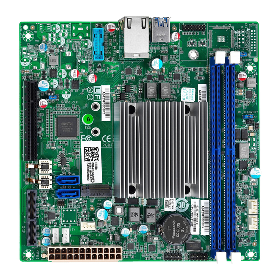
Page 16: Board Image
2.1 Board Image S3227 (ATX Power Support) This picture is representative of the latest board revision available at the time of publishing. The board you receive may not look exactly like the above picture. http://www.tyan.com... - Page 17 S3227 (DC12V Power Support) This picture is representative of the latest board revision available at the time of publishing. The board you receive may not look exactly like the above picture. http://www.tyan.com...
-
Page 18: Block Diagram
2.2 Block Diagram S3227 Block Diagram http://www.tyan.com... -
Page 19: Mainboard Mechanical Drawing
2.3 Mainboard Mechanical Drawing http://www.tyan.com... -
Page 20: Board Parts, Jumpers And Connectors
The board you receive may not look exactly like the above diagram. But for the DIMM number please refer to the above placement for memory installation. For the latest board revision, please visit our web site at http://www.tyan.com. http://www.tyan.com... - Page 21 PCIE (x8) (J10) Clear CMOS Jumper (J11) SFI Connector (J28) ME Recovery Setting Jumper (J37) P0_MC0_ DIM_CH_A0 (J8C1) Chassis Intrusion Header (J19) P0_MC0_ DIM_CH_B0 (J8C2) Jumper Legend OPEN - Jumper OFF Without jumper cover CLOSED - Jumper ON With jumper cover http://www.tyan.com...
- Page 22 J21 / J24: 7-pin SATA Connector support up to SATA III PIN Define Connects to the Serial SATA_TXP_C ATA ready drives via SATA_TXN_C the Serial ATA cable. SATA_RXN_C J21: SATA1 SATA_RXP_C J24: SATA0 J19: Chassis Intrusion Header Signal Signal Intrusion Header http://www.tyan.com...
- Page 23 KEY-Pin LAD0 LAD1 PCIRST_N LAD2 LAD3 CLKRUN SERIRQ VCC3_STB J37: ME Recovery Setting Jumper Pin1-2 closed: Normal (Default) Pin2-3 closed: ME Recover J38: ME Security Override Jumper Pin1-2 closed: No Flash Security Override (Default) Pin2-3 closed: Flash Security Override http://www.tyan.com...
- Page 24 3. Move the jumper cap to close Pin_2 and Pin_3 for several seconds to Clear CMOS. 4. Put jumper cap back to Pin_1 and Pin_2 (Default setting). Clear CMOS 5. Reconnect power connectors to the motherboard and power on system. http://www.tyan.com...
-
Page 25: Tips On Installing Motherboard In Chassis
Some chassis include plastic studs instead of metal. Although the plastic studs are usable, MiTAC recommends using metal studs with screws that will fasten the motherboard more securely in place. Below is a chart detailing what the most common motherboard studs look like and how they should be installed. http://www.tyan.com... - Page 26 http://www.tyan.com...
-
Page 27: Installing The Memory
2.6 Installing the Memory Before installing memory, ensure that the memory you have is compatible with the motherboard and processor. Check the TYAN Web site at http://www.tyan.com details of the type of memory recommended for your motherboard. Supports two DDR4 slots,... - Page 28 Memory Installation Procedure Follow these instructions to install memory modules into the S3227. Unlock the clips as shown in the illustration. Insert the memory module firmly into the socket by gently pressing down until it sits flush with the socket.
-
Page 29: Installing The M3227L8-X557-2C Lan Card (Optional)
LAN card. 2. Unscrew and then remove the support bracket from the chassis. 3. Align and connect the LAN card to the PCIe and OCP slots on the motherboard. Secure the LAN card to the chassis with the screw. http://www.tyan.com... -
Page 30: Attaching Drive Cables
2.8 Attaching Drive Cables Attaching Serial ATA Cables S3227 is equipped with two (2) Serial ATA (SATA) channel. Connections for the drives are very simple. There is no need to set Master/Slave jumpers on SATA drives. If you are in need of SATA/SAS cables or power adapters please contact your place of purchase. -
Page 31: Installing Add-In Cards
Doing so allows air to circulate within the chassis more easily, thus improving cooling for all installed devices. NOTE: You must always unplug the power connector to the motherboard before performing system hardware changes to avoid damaging the board or expansion device. http://www.tyan.com... -
Page 32: Connecting External Devices
Connecting external devices to the motherboard is an easy task. The motherboard supports a number of different interfaces through connecting peripherals. See the following diagrams for the details. NOTE: Peripheral devices can be plugged straight into any of these ports but software may be required to complete the installation. http://www.tyan.com... - Page 33 10/100/1000 Mbps LAN Link/Activity LED Scheme Left LED Right LED Link Green 10 Mbps Active Blinking Green Solid Green Link Green 100 Mbps Solid Green Active Blinking Green Solid Yellow Link Green 1000 Mbps Solid Yellow Active Blinking Green No Link http://www.tyan.com...
-
Page 34: Installing The Power Supply
2.11 Installing the Power Supply There is three (3) power connector on your S3227 motherboard. The S3227 supports EPS 12V power supply. PW3: ATX 24-pin Main Power Connector Signal Signal +3.3V +3.3V +3.3V -12V PS ON# Power OK Reserved +5VSB... -
Page 35: Installing The Power Cable
2.12 Installing the Power Cable a. Non S32272NR-M2-D12 only b. For S32272NR-M2-D12 only NOTE: Please purchase the Delta (DPS-65VB A) Adapter for DC power support separately. http://www.tyan.com... -
Page 36: Finishing Up
In the rare circumstance that you have experienced difficulty, you can find help by asking your vendor for assistance. If they are not available for assistance, please find setup information and documentation online at our website or by calling your vendor’s support line. http://www.tyan.com... -
Page 37: Chapter 3: Bios Setup
The table below shows how to navigate in the setup program using the keyboard. Function Left/Right Arrow Keys Change from one menu to the next Up/Down Arrow Keys Move between selections Enter Open highlighted section PgUp/PgDn Keys Change pages Change options Exit http://www.tyan.com... - Page 38 The following pages provide the details of BIOS menu. Please be noticed that the BIOS menu are continually changing due to the BIOS updating. The BIOS menu provided are the most updated ones when this manual is written. Please visit TYAN’s website at http://www.tyan.com for the information of BIOS updating. http://www.tyan.com...
-
Page 39: Main Menu
This displays the total memory size. System Language Choose the system default language. English System Date Adjust the system date. MM (Months): DD (Days): YYYY (Years) System Time Adjust the system clock. HH (24 hours format): MM (Minutes): SS (Seconds) http://www.tyan.com... -
Page 40: Advanced Menu
Trusted Computing Trusted Computing Settings. ACPI Settings System ACPI Parameters. Onboard Device Configuration Onboard Device Configuration. WatchDog Timer Configuration WatchDog Configuration. Super IO Configuration System Super IO Chip Parameters. Hardware Health Configuration / H/W Monitor Hardware health Configuration Parameters. http://www.tyan.com... - Page 41 Get driver information and configure Realtek Ethernet controller parameter. NOTE: The submenu will appear when a Realtek Ethernet chip is installed. Intel® Etehrnet Connection X553/X557-AT 10GBASE-T) Configure 10 Gigabit Ethernet device parameters. NOTE: The submenu will appear when an Intel Ethernet chip is installed. http://www.tyan.com...
- Page 42 3.3.1 Trusted Computing Security Device Support Enables or Disables BIOS support for security device. O.S. will not show Security Device. TCG EFI protocol and INT1A interface will not be available. Enabled / Disabled http://www.tyan.com...
- Page 43 3.3.2 ACPI Settings Enable ACPI Auto Configuration Enables or Disables BIOS ACPI Auto Configuration. Disabled / Enabled Enable Hibernation Enable or disable System ability to Hibernate (OS/S4 Sleep State). This option may not be effective with some OS. Disabled / Enabled http://www.tyan.com...
- Page 44 3.3.3 OnBoard Device Configuration Chassis Intrusion detect ENABLED: When a chassis open event is detected, the BIOS will record the event. Disabled / Enabled http://www.tyan.com...
- Page 45 Disabled / POST / OS / PowerON NOTE: Watch Dog Timer will not appear when Watch Dog Mode is set to [Disabled]. Watch Dog Timer Watch Dog Timer Help. 2 MINS / 4 MINS / 6 MINS / 8 MINS / 10 MINS http://www.tyan.com...
- Page 46 3.3.5 Super IO Configuration Super IO Chip Read only. http://www.tyan.com...
- Page 47 / IO=3F8h, IRQ=3, 4, 5, 6, 7, 9, 10, 11, 12; / IO=2F8h; IRQ=3, 4, 5, 6, 7, 9, 10, 11, 12; / IO=3E8h, IRQ=3, 4, 5, 6, 7, 9, 10, 11, 12; / IO=2E8h, IRQ=3, 4, 5, 6, 7, 9, 10, 11, 12; http://www.tyan.com...
- Page 48 3.3.6 Hardware Health Configuration Auto Fan Control Automatic Fan Control. Disabled: Fan speed full on. Enabled: Automatic fan speed control by temperature. Disabled / Enabled Deep S5 Enable/Disabled Deep S5 Function. Disabled / Enabled http://www.tyan.com...
- Page 49 3.3.6.1 Sensor Data Register Monitoring Read only. http://www.tyan.com...
- Page 50 Wake system from S5 Enable or disable System wake on alarm event. Select Fixed Time, system will wake on the hr:min:sec specified. Select Dynamic Time, system will wake on the current time + increase minute(s). Disabled / Fixed Time / Dynamic Time http://www.tyan.com...
- Page 51 COM1 / Serial Port for Out-Of-Band Management/Windows Emergency Services (EMS) Console Redirection Settings The settings specify how the host computer (which the user is using) will exchange data. Both computers should have the same or compatible settings. Legacy Console Redirection Settings Legacy Console redirection settings. http://www.tyan.com...
- Page 52 1’s in the data bits is odd. Mark: parity bit is always 1. Space: parity bit is always 0. Mark and Space parity do not allow for error detection. None / Even / Odd / Mark / Space http://www.tyan.com...
- Page 53 On this mode enabled only text will be sent. This is to capture Terminal data. Disabled / Enabled Resolution 100x31 Enable or disable extended terminal resolution. Disabled / Enabled Putty KeyPad Select FunctionKey and KeyPad on Putty. VT100 / LINUX / XTERMR6 / SCO / ESCN / VT400 http://www.tyan.com...
- Page 54 Redirection after POST The settings specify if BootLoader is selected than Legacy console redirection is disabled before booting to Legacy OS. Default value is Always Enable which means Legacy Console Redirection is enabled for Legacy OS. Always Enable / BootLoader http://www.tyan.com...
- Page 55 VT-UTF8 / VT100 / VT100+ / ANSI Bits per Second Select serial port transmission speed. The speed must be matched on the other side. Long or noisy lines may require lower speeds. 115200 / 9600 / 19200 / 57600 http://www.tyan.com...
- Page 56 ‘start’ signal can be sent to restart the flow. Hardware flow control uses two wires to send start/stop signal. None / Hardware RTS/CTS / Software Xon/Xoff Data Bits / Parity / Stop Bits Read only. http://www.tyan.com...
- Page 57 3.3.9 Option ROM Dispatch Policy OnBoard LAN1 (X557) / LAN2 (X557) X557 Option ROM Setting. Enabled / Disabled OnBoard LAN3 (Realtek) / LAN4 (Realtek) Realtek Option ROM Setting. Enabled / Disabled http://www.tyan.com...
- Page 58 Enables or Disables 64bit capable Devices to be Decoded in Above 4G Address Space (Only if System Supports 64 bit PCI Decoding). Disabled / Enabled SR-IOV Support If system has SR-IOV capable PCIe Devices, this option enables or disables Single Root IO Virtualization Support. Disabled / Enabled http://www.tyan.com...
- Page 59 Auto / 128 Bytes / 256 Bytes / 512 Bytes / 1024 Bytes / 2048 Bytes / 4096 Bytes ASPM Support Set the ASPM Level: ForceL0s – Force all links to L0s State Auto – BIOS auto configure DISABLE – Disables ASPM Disabled / Auto / Force L0s http://www.tyan.com...
- Page 60 Enable Ipv6 PXE Boot Support. If disabled IPV6 PXE boot option will not be created. Disabled / Enabled Ipv6 HTTP Support Enable Ipv6 HTTP Boot Support. If disabled IPV6 HTTP boot option will not be created. Disabled / Enabled http://www.tyan.com...
- Page 61 PXE boot wait time Wait time to press ESC key to abort the PXE boot. Media detect count Number of times presence of media will be checked. http://www.tyan.com...
- Page 62 Legacy / Do not launch / UEFI Storage Controls the execution of UEFI and Legacy Storage OpROM. Legacy / Do not launch / UEFI Video Controls the execution of UEFI and Legacy Video OpROM Legacy / Do not launch / UEFI http://www.tyan.com...
- Page 63 Other PCI Devices Determines OpROM execution policy for devices other than Network, Storage, or Video. Legacy / Do not launch / UEFI http://www.tyan.com...
- Page 64 XHCI Hand-off This is a workaround for OSes without XHCI hand-off support. The XHCI ownership change should be claimed by XHCI driver. Enabled / Disabled USB Mass Storage Driver Support Enable/Disable USB Mass Storage Driver Support. Enabled / Disabled http://www.tyan.com...
- Page 65 JetFlashTranscend 64G Mass Storage device emulation type. ‘AUTO’ enumerates devices according to their media format. Optical drives are emulated as ‘CDROM’, drives with no media will be emulated. Auto / Floppy / Forced FDD / Hard Disk / CD-ROM http://www.tyan.com...
- Page 66 3.3.14 Realtek PCIe GBE Family Controller (MAC: AO: …) Read only. http://www.tyan.com...
- Page 67 3.3.15 Intel(R) Ethernet Connection (X553/X557-AT 10GBASE-T) Blink LEDs Identify the physical network port by blinking the accosicated LED. http://www.tyan.com...
- Page 68 3.3.15.1 NIC Configuration Wake on LAN Enables power on of the system via LAN. Note that configuring Wake on LAN in the operating system does not change the value of this setting, but does override the behavior. Enabled / Disabled http://www.tyan.com...
-
Page 69: Intel Rc Setup
3.4 Intel RC Setup Relax Security Configuration Relaxes the security configuration to be able to use BIOS update tools. Enabled / Disabled http://www.tyan.com... - Page 70 Enables the Enhanced Cx state of the CPU, takes effect after reboot. Auto – Enable for B0 CPU stepping, all others disabled, change setting to override. Enabled / Disabled Package C State limit Package C State limit. No Pkg C-State / No S0In / No Limit http://www.tyan.com...
- Page 71 Options are: C1 and C6. C6 / C1 Execute Disable Bit When disabled, forces the XD feature flag to always return 0. Enabled / Disabled Enables the Vanderpool Technology, takes effect after reboot. Enabled / Disabled AES-NI Enable/Disable AES-NI support. Enabled / Disabled http://www.tyan.com...
- Page 72 3.4.2 Server ME Configuration http://www.tyan.com...
- Page 73 ECC Support Select to enable/disable ECC Support. Disabled / Enabled Select Refresh Rate Disable, 1x, 2x or 4x options available. Disabled / 1x/2x / 1x/2x/4x / 2x / 4x VT-d Option to Enable / Disable VT-d. Disabled / Enabled http://www.tyan.com...
- Page 74 3.4.6 South Bridge Chipset Configuration State After G3 Specify what state to go to when power is re-applied after a power failure (G3 state). S0 State / S5 State / Soft Strap http://www.tyan.com...
- Page 75 3.4.6.1 SATA Configuration SATA 0 Configuration of SATA Controller. http://www.tyan.com...
- Page 76 3.4.6.1.1 SATA0 Enable Controller Enables/Disables SATA controller if supported by current CPU SKU. Enabled / Disabled Enables/Disables Link Power Management. Enabled / Disabled http://www.tyan.com...
- Page 77 3.4.6.1.1.1 M2 SATA Port / Port1~Port2 Enable/disable port Enables/Disables SATA controller if supported by current CPU SKU. Enabled / Disabled Hot Plug Hot plug. Enabled / Disabled Spin Up Spin up. Enabled / Disabled http://www.tyan.com...
- Page 78 3.4.6.2 USB Configuration USB Precondition Precondition work on USB host controller and root ports for faster enumeration. Enabled / Disabled XHCI Compliance Mode Disable Compliance Mode. Disabled / Enabled http://www.tyan.com...
-
Page 79: Event Log
3.5 Event Log Change Smbios Event Log Settings Press <Enter> to change the Smbios Event Log configuration. View Smbios Event Log Press <Enter>.to view the Smbios Event Log records. http://www.tyan.com... - Page 80 Choose options for erasing Smbios Event Log. Erasing is done prior to any logging activation during reset. No / Yes, Next reset / No, Every reset When Log is Full Choose options for reactions to a full Smbios Event Log. Do Nothing / Erase Immediately http://www.tyan.com...
- Page 81 3.5.2 View Smbios Event Log Read only. http://www.tyan.com...
-
Page 82: Security
Set user password in the Create New Password window. After you key in the password, the Confirm New Password window will pop out to ask for confirmation. Security Frozen Mode This function only support PCH AHCI SATA ports, not for USB device. Enabled / Disabled http://www.tyan.com... - Page 83 Secure Boot activated when Platform Key (PK) is enrolled, System mode is User/Deployed, and CSM function is disabled. Disabled / Enabled Secure Boot Mode Secure Boot mode selector: Standard/Custom. In Custom mode Secure Boot Variables can be configured without authentication. Standard / Custom http://www.tyan.com...
- Page 84 Save NVRAM content of all Secure Boot variables to the files (EFI_SIGNATURE_LIST data format) in root folder on a target file system device. Platform Key (PK) Enroll Factory Defaults or load certificates from a file: 1. Public Key Certificate in: a) EFI_SIGNATURE_LIST b) EFI_CERT_X509 (DER encoded) http://www.tyan.com...
- Page 85 Key source: Default, Custom, Mixed (*) modified from Setup menu Set New / Append Authorized TimeStamps Enroll Factory Defaults or load certificates from a file: 1. Public Key Certificate in: a) EFI_SIGNATURE_LIST b) EFI_CERT_X509 (DER encoded) c) EFI_CERT_RSA2048 (bin) d) EFI_CERT_SHA256 (bin) 2. Authenticated UEFI Variable http://www.tyan.com...
- Page 86 Enroll Factory Defaults or load certificates from a file: 1. Public Key Certificate in: a) EFI_SIGNATURE_LIST b) EFI_CERT_X509 (DER encoded) c) EFI_CERT_RSA2048 (bin) d) EFI_CERT_SHA256 (bin) 2. Authenticated UEFI Variable Key source: Default, Custom, Mixed (*) modified from Setup menu Set New / Append http://www.tyan.com...
-
Page 87: Boot
Enable or disable Quiet Boot option. Disabled / Enabled Boot Option #1 ~ #5 Set the system boot order. UEFI: SanDisk (Device name) / Disabled Wait for ‘ESC’ If Error Wait for ‘ESC’ key to be pressed if error occurs. Disabled / Enabled http://www.tyan.com... - Page 88 Endless Boot Enable or Disable Endless boot. Disabled / Enabled http://www.tyan.com...
- Page 89 3.7.1 Delete Boot Option Delete Boot Option Remove an EFI boot option from the boot order. Select one to Delete http://www.tyan.com...
-
Page 90: Save & Exit
Reset the system after saving the changes. Discard Changes and Reset Reset system setup without saving any changes. Save Changes Save changes done so far to any of the setup options. Discard Changes Discard changes done so far to any of the setup options. http://www.tyan.com... - Page 91 UEFI: PXE IP4 Intel® Ethernet Connection UEFI: PXE IP4 Intel® Ethernet Connection UEFI: Built-in EFI Shell UEFI: JetFlashTranscend 64GB 1100, Partition 1 Launch EFI Shell from filesystem device Attempts to Launch EFI Shell application (Shell.efi) from one of the available filesystem devices. http://www.tyan.com...
- Page 92 NOTE http://www.tyan.com...
-
Page 93: Chapter 4: Diagnostics
BIOS flash failure, you must contact your dealer for a replacement BIOS. There are no exceptions. TYAN does not have a policy for replacing BIOS chips directly with end users. In no event will TYAN be held responsible for damages done by the end user. -
Page 94: Amibios Post Code (Aptio)
South Bridge initialization before microcode loading 0x05 OEM initialization before microcode loading 0x06 Microcode loading 0x07 AP initialization after microcode loading 0x08 North Bridge initialization after microcode loading 0x09 South Bridge initialization after microcode loading 0x0A OEM initialization after microcode loading 0x0B Cache initialization http://www.tyan.com... - Page 95 CPU post-memory initialization is started 0x33 CPU post-memory initialization. Cache initialization 0x34 CPU post-memory initialization. Application Processor(s) (AP) initialization 0x35 CPU post-memory initialization. Boot Strap Processor (BSP) selection 0x36 CPU post-memory initialization. System Management Mode(SMM) initialization 0x37 Post-Memory North Bridge initialization is started http://www.tyan.com...
- Page 96 Reserved for future AMI progress codes S3 Resume Error Codes 0xE8 S3 Resume Failed 0xE9 S3 Resume PPI not Found 0xEA S3 Resume Boot Script Error 0xEB S3 OS Wake Error 0xEC – 0xEF Reserved for future AMI error codes http://www.tyan.com...
- Page 97 CPU DXE initialization (CPU module specific) 0x67 CPU DXE initialization (CPU module specific) 0x68 PCI host bridge initialization 0x69 North Bridge DXE initialization is started 0x6A North Bridge DXE SMM initialization is started 0x6B North Bridge DXE initialization (North Bridge module specific) http://www.tyan.com...
- Page 98 USB initialization is started 0x9B USB Reset 0x9C USB Detect 0x9D USB Enable 0x9E -0x9F Reserved for future AMI codes 0xA0 IDE initialization is started 0xA1 IDE Reset 0xA2 IDE Detect 0xA3 IDE Enable 0xA4 SCSI initialization is started http://www.tyan.com...
- Page 99 No Console Output Devices are found 0xD7 No Console Input Devices are found 0xD8 Invalid password 0xD9 Error loading Boot Option (LoadImage returned error) 0xDA Boot Option is failed (StartImage returned error) 0xDB Flash update is failed 0xDC Reset protocol is not available http://www.tyan.com...
- Page 100 System is waking up from the S3 sleep state 0x40 System is waking up from the S4 sleep state 0xAC System has transitioned into ACPI mode. Interrupt controller is in PIC mode. 0xAA System has transitioned into ACPI mode. Interrupt controller is in APIC mode. http://www.tyan.com...
-
Page 101: Appendix I: Fan And Temp Sensors
The red mark indicates the sensor. Fan and Temp Sensor Location: Fan Sensor: It is located in the third pin of the fan connector, which detects the fan speed (rpm) Temp Sensor: CPU_Area_Temp, CPU_MOS_Area, P0_MC0_DIM_CH_A0 and P0_MC0_DIM_CH_B0. Temp sensor detects the system temperature around. http://www.tyan.com... - Page 102 CPU_ Area_Temp Temperature of the CPU Area CPU_ MOS_Area Temperature of the CPU MOS Area P0_MC0_DIM_CH_A0 Temperature of DIMM_A0 Slot P0_MC0_DIM_CH_B0 Temperature of DIMM_B0 Slot CPU_FAN Fan Speed of CPU_FAN SYS_FAN_1 Fan Speed of SYS_FAN_1 SYS_FAN_2 Fan Speed of SYS_FAN_2 http://www.tyan.com...
-
Page 103: Appendix Ii: Com Port Configuration For Vga Support
Hardware Cables: Please prepare the following cables for COM Port Cable Connection. a. RS232 cable (S3227 MB COM1 Header to COM Port) b. Null Modem Cable (COM Port to COM Port) c. COM to USB Cable (COM Port to Computer’s Type-A USB Port) - Page 104 The following diagram shows how to establish the COM Port Cable Connection. 3. Configure COM Port Settings To enable the VGA function, configure the default settings as below: a. Check the Host side COM Port number from your computer. http://www.tyan.com...
- Page 105 Check the BIOS Serial Port Console Redirection Settings as below. Click Tab Advanced Serial Port Console Redirection COM1 Console Redirection Settings http://www.tyan.com...
- Page 106 Click the Serial Port Monitor utility and the following dialog box will pop out. Here we use “Tera Term’ utility for demonstration. Port: Select COM4. Baud rate: Select 115200. d. Click OK to finish. http://www.tyan.com...
-
Page 107: Glossary
(reading to or writing from a disk drive a single time is much faster than doing so repeatedly) there is the possibility of losing your data should the system crash. Information in a buffer is temporarily stored, not permanently saved. http://www.tyan.com... - Page 108 (like soundcards or keyboards) to access the main memory without involving the CPU. This frees up CPU resources for other tasks. As with IRQs, it is vital that you do not double up devices on a single line. Plug-n-Play devices will take care of this for you. http://www.tyan.com...
- Page 109 EEPROM (Electrically Erasable Programmable ROM): also called Flash BIOS, it is a ROM chip which can, unlike normal ROM, be updated. This allows you to keep ® up with changes in the BIOS programs without having to buy a new chip. TYAN ’s BIOS updates can be found at http://www.tyan.com...
- Page 110 PXE (Preboot Execution Environment): one of four components that together make up the Wired for Management 2.0 baseline specification. PXE was designed to define a standard set of preboot protocol services within a client with the goal of allowing networked-based booting to boot using industry standard protocols. http://www.tyan.com...
- Page 111 NVIDIA s (graphics communications processing units) and NVIDIA MCPs (media and processors). application Depending on the , NVIDIA SLI can deliver as much as two times the performance of a single GPU configuration. http://www.tyan.com...
- Page 112 CPUs without damaging the sensitive CPU pins. The CPU is lightly placed in an open ZIF socket, and a lever is pulled down. This shifts the processor over and down, guiding it into the board and locking it into place. http://www.tyan.com...
-
Page 113: Technical Support
(which can have expensive consequences). If these options are not available for you then TYAN can help. Besides designing innovative and quality products for over a decade, TYAN has continuously offered customers service beyond their expectations. - Page 114 (RMA) number. The RMA number Should be prominently displayed on the outside of the shipping carton and the package should be mailed prepaid. TYAN will pay to have the board shipped back to you. Notice for the USA Compliance Information Statement (Declaration of...