
Related Manuals for LD LDU300


Summary of Contents for LD LDU300
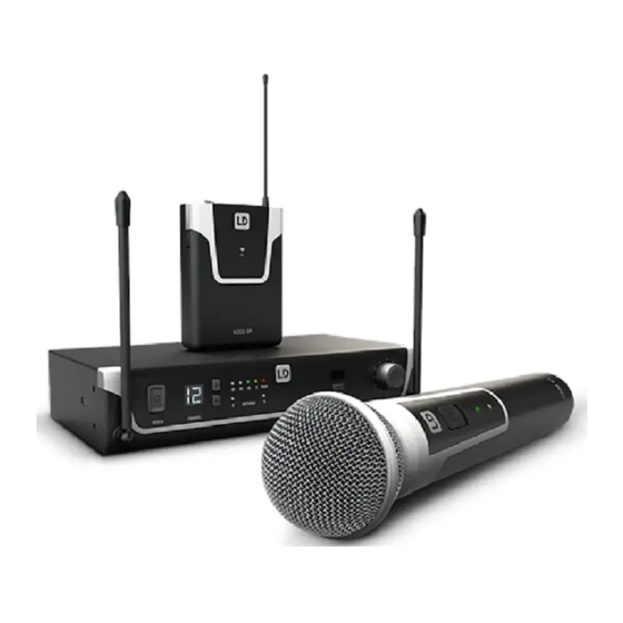
- Page 1 USER´S MANUAL BEDIENUNGSANLEITUNG MANUEL D´UTILISATION MANUAL DE USUARIO INSTRUKCJA OBSŁUGI MANUALE D´USO Includes Wireless microphone system Adam Hall GmbH. Model: LDU300/ LDU500...
-
Page 2: Table Of Contents
CONTENTS ENGLISH PREVENTIVE MEASURES INTRODUCTION CONNECTIONS, OPERATING AND DISPLAY ELEMENTS PIN ALLOCATION FOR MINI XLR CONNECTOR (POCKET TRANSMITTER) TROUBLESHOOTING OPTIONAL ACCESSORIES 10-11 TECHNICAL DATA 11-13 MANUFACTURER’S DECLARATIONS... -
Page 3: English
YOU‘VE MADE THE RIGHT CHOICE! We have designed this product to operate reliably over many years. LD Systems stands for this with its name and many years of experience as amanufacturer of high-quality audio products.Please read this User‘s Manual carefully,so that you can begin makingoptimum use of your LD Systems product quickly. -
Page 4: Introduction
CAUTION: Toreduce the riskof electric shock,do not remove cover (or back).There are no user serviceable parts inside.Maintenanceandrepairsshouldbe exclusivelycarriedoutby qualifiedservicepersonnel. The warning triangle with lightning symbol indicates dangerous uninsulated voltage inside the unit, which may cause an electrical shock. The warning triangle with exclamation mark indicates important operating and maintenance instructions. Warning! This symbol indicates a hot surface. -
Page 5: Connections, Operating And Display Elements
• Available in the following frequencies:470-542MHz (LDU 504.7/LDU 505.1/LDU 305.1/LDU 304.7) Please note: The use of the wireless microphone system may require a license, depending on the country of use. For detailed information please contact the relevant authority in your country. Pilot tone The pilot tone function protects a wireless microphone system against interference, for example, unwanted signals from other radio trans- mission systems. - Page 6 Rotary knob to adjust the output volume. IR INTERFACE Infra-red interface for synchronising the receiver’s radio channel with the transmitter. Tosynchronisethe transmitterwith the radio channelsetinthe receiver,position theinfra-red portofthe transmitterdirectly inlinewiththe infra-red interface ofthe receiverand switch onthe transmitterandreceiver(distance about10cm,IRinterfaceof the handtransmitteris below the status LED,IR interface of the pocket transmitter on the front side).Now press theASC button to start the synchronisation process.A red LED indicator will light up in the window of the IR interface during the process.After a few seconds, the process is completed and one of the LED indicators ANTENNA A and B will light up (= wireless connection exists).
- Page 7 Balanced audio output via 3-pin XLR jack. HAND-HELD TRANSMITTER MICROPHONE HEAD The microphone head is interchangeable, the hand-held transmitter is compatible with the microphone heads from the LD U500® series, available separately. ON / OFF On/off switch. Move the switch to the ON position to turn on the hand-held transmitter, and to the OFF position to turn it off.
- Page 8 21 Antenna Pocket transmitter antenna. For optimum reception, do not cover or kink. IR INTERFACE Infra-red interface for synchronising the radio channel from receiver and transmitter. INPUT 3-pin mini XLR socket to connect a headset, Lavalier or instrument microphone and guitar cable. ON / STANDBY / OFF Switch to activate or deactivate the pocket transmitter (ON = transmitter is switched on, OFF = transmitter is switched off).
-
Page 9: Pin Allocation For Mini Xlr Connector (Pocket Transmitter)
BATTERY COMPARTMENT Toreplace the batteries, open the battery compartment of the pocket transmitter by simultaneously pressing both markers on the sides of the battery cover and opening it forwards. Remove theused batteries and replace with new batteries (AA/LR6,alkaline), following the diagram in the battery compartment. -
Page 10: Troubleshooting
TROUBLESHOOTING PROBLEM SYMPTOM SOLUTION No audio signal or level Receiver: No reception displayed on either antenna Check if the transmitter is turned on. too low A or B. Check the batteries in the transmitter. Receiver: Display lighting is switched off Checkthepowersupplyforthereceiverandwhether the receiver is switchedon. -
Page 11: Technical Data
LDU500RK2–19"rackmountingkitfortheinstallationoftwosinglereceivers(2rack-mountbrackets,2connectorsand1setofscrews included). Installation 1. Attach connectors (receiver A on the right-hand side, receiver B on the left-hand side). 2. Screw both receivers together. 3. Attach brackets (receiver A on the left-hand side, receiver B on the right-hand side). TECHNICAL DATA RECEIVER Item number: LDU 500... - Page 12 Unbalanced output: 6.3 mm jack 6.3 mm jack Audio output level +10dBu +10dBu (balanced): Audio output level +7dBV/+2.5dBV +7dBV/+2.5dBV (unbalanced): (switchable line/instrument) (switchable line/instrument) Controls: POWER, + / - channel select, POWER, + / - channel select, ASC, VOL volume control, switch ASC, VOL volume control, switch INSTRUMENT/LINE INSTRUMENT/LINE...
- Page 13 BODY PACK TRANSMITTER Item number: LDU 504 . 7 BP / LDU 505.1 BP LDU 305.1 BP/ LDU 304.7 BP Modulation: Frequency range: 470-542MHz 470-542MHz Channels: Input: 3-pin mini-XLR 3-pin mini-XLR (low-Z + phantom power/high-Z) (low-Z + phantom power/high-Z) Frequency response: 25–16,000 Hz 25–16,000 Hz RF output power:...
-
Page 14: Manufacturer's Declarations
MANUFACTURER´S DECLARATIONS MANUFACTURER‘S WARRANTY & LIMITATIONS OF LIABILITY You can find our current warranty conditions and limitations of liability at: https://cdn-shop.adamhall.com/media/pdf/MANUFACTU- RERS-DECLARATIONS_LD_SYSTEMS.pdf. To request warranty service for a product, please contact Adam Hall GmbH, Adam-Hall-Str. 1, 61267 Neu Anspach / Email: Info@adamhall.com / +49 (0)6081 / 9419-0. CORRECT DISPOSAL OF THIS PRODUCT (valid in the European Union and other European countries with a differentiated waste collection system) This symbol on the product, or on its documents indicates that the device may not be treated as household waste.This is to avoid... - Page 15 LD-SYSTEMS.COM Adam Hall GmbH | Adam-Hall-Str. 1 | 61267 Neu-Anspach | Germany Phone: +49 6081 9419-0 | adamhall.com REV: 04...
- Page 16 FCC Statement This equipment has been tested and found to comply with the limits for a Class B digital device, pursuant to part 15 of the FCC Rules. These limits are designed to provide reasonable protection against harmful interference in a residential installation. This equipment generates, uses and can radiate radio frequency energy and, if not installed and used in accordance with the instructions, may cause harmful interference to radio communications.
Need help?
Do you have a question about the LDU300 and is the answer not in the manual?
Questions and answers