Download Print this page
Sharp E630U Service Manual

Sharp E630U Service Manual

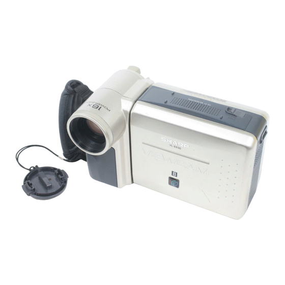
Liquid crystal camcorder

Advertisement

In this Service Manual, only the differences from VL-E610U/660U/665U
(S28L7VL-E610U) are described.
Therefore, for the parts which are not described in this Service Manual, refer
to the Service Manual for VL-E610U/660U/665U (S28L7VL-E610U) and its
supplement version (S38N9VL-E610U).
2. SPECIFICATIONS .............................................................................................................................. 2
4. DISASSEMBLY OF THE SET ............................................................................................................. 3
5. MECHANISM ADJUSTMENT ............................................................................................................. 4
6. ADJUSTMENT OF VCR ...................................................................................................................... 5
8. SCHEMATIC DIAGRAMS .................................................................................................................. 8
11.REPLACEMENT PARTS LIST .......................................................................................................... 29
12.PACKING OF THE SET .................................................................................................................... 35
SHARP CORPORATION
SERVICE MANUAL
LIQUID CRYSTAL CAMCORDER
MODELS
In the interests of user-safety (Required by safety regula-
tions in some countries) the set should be restored to its
original condition and only parts identical to those specified
be used.
CONTENTS
This document has been published to be used for
after sales service only.
The contents are subject to change without notice.
1
SY8A5VL-E630U
8
VL-E630U/T
VL-E680U
VL-E685U/T
Page
VL-E630U/T
VL-E630U/T
VL-E680U
VL-E680U
VL-E685U/T
VL-E685U/T
NTSC

Advertisement

loading

Summary of Contents for Sharp E630U

  • Page 1: Table Of Contents

    VL-E630U/T VL-E630U/T VL-E680U VL-E680U VL-E685U/T VL-E685U/T SERVICE MANUAL SY8A5VL-E630U LIQUID CRYSTAL CAMCORDER NTSC VL-E630U/T VL-E680U VL-E685U/T MODELS In the interests of user-safety (Required by safety regula- tions in some countries) the set should be restored to its original condition and only parts identical to those specified be used.
  • Page 2: Specifications

    *Minimum illumination: Since there is no widely accepted testing procedure for determining minimum illumina- tion capability, lux ratings are comparable only between models from the same For the location of the nearest Sharp Authorized Service, or to obtain product literature, accessories, manufacturer.
  • Page 3: Disassembly Of The Set

    VL-E630U/T VL-E680U VL-E685U/T 4. DISASSEMBLY OF THE SET Area A 4-2. Disassembly of the VCR main body 1. Removal of the VCR lid shaft (1)Remove one screw ((j)LX-HZ0063TAFC). 4-3. REPLACEMENT OF CCD SENSOR 4-3-1. BEFORE REPLACEMENT 1) The CCD image sensor is more sensitive to electrostatic breakage than C-MOS LSI. Therefore sufficient means to prevent electrostatic damage must be taken when it is replaced.
  • Page 4: Mechanism Adjustment

    VL-E630U/T VL-E680U VL-E685U/T 5. MECHANISM ADJUSTMENT 5-2. Items and timings of inspection and maintenance 5-2-1. Inspection and maintenance list Usage time (hrs.) Possible symptom Checking/Maintenance point Remarks encountered 500 1,000 1,500 2,000 3,000 Tape travelling route • Lateral noise Rollers (Refer to Section) •...
  • Page 5: Adjustment Of Vcr

    VL-E630U/T VL-E680U VL-E685U/T 6. ADJUSTMENT OF VCR 6-1. ADJUSTMENT OF VCR SECTION 6-1-5. Y/C circuit adjustment method 3. Adjustment of playback Y level Measuring instrument Oscilloscope Mode Playback signal Color bar (JiGWR5-5NSP) 500±20mVp-p Measuring point TL801 Adjustment address 27 500 ± 20 mVp-p Adjustment level 5.
  • Page 6 VL-E630U/T VL-E680U VL-E685U/T Preparation for 6-2-2-3~6-2-2-9; set up the camera signal adjustment mode. (Write 00 to the address 1FE.) 6-2-2-3. Before starting these adjustments, set up the auto focus adjust. • Sync level adjustment Video Measuring instrument Oscilloscope Subject Anything Tape —...
  • Page 7 VL-E630U/T VL-E680U VL-E685U/T - M E M O -...
  • Page 8: Schematic Diagrams

    VL-E630U/T VL-E630U/T VL-E680U VL-E680U VL-E685U/T VL-E685U/T 8. SCHEMATIC DIAGRAM å AND SHADED COMPONENTS=SAFETY RELATED PARTS 8-2. POWER CIRCUIT SCHEMATIC DIAGRAM å å 8~11...
  • Page 9 VL-E630U/T VL-E680U VL-E685U/T 8-3. AUDIO CIRCUIT SCHEMATIC DIAGRAM...
  • Page 10 VL-E630U/T VL-E680U VL-E685U/T 8-4. MOTOR DRIVER SCHEMATIC DIAGRAM...
  • Page 11 VL-E630U/T VL-E630U/T VL-E680U VL-E680U VL-E685U/T VL-E685U/T 8-5. LCD DISPLAY CIRCUIT SCHEMATIC DIAGRAM * See (S38N9VL-E610U) Page 8-23 When replacing the IC800 14~17...
  • Page 12 VL-E630U/T VL-E630U/T VL-E680U VL-E680U VL-E685U/T VL-E685U/T 8-6. RF CIRCUIT SCHEMATIC DIAGRAM 18~19...
  • Page 13 VL-E630U/T VL-E630U/T VL-E680U VL-E680U VL-E685U/T VL-E685U/T 8-7. SYSTEM CONTROL CIRCUIT SCHEMATIC DIAGRAM * See (S38N9VL-E610U) Page 8-24 When replacing the IC703,705 20~23...
  • Page 14 VL-E630U/T VL-E630U/T VL-E680U VL-E680U VL-E685U/T VL-E685U/T 8-9. Y/C CIRCUIT SCHEMATIC DIAGRAM * See (S38N9VL-E610U)Page 8-23 When replacing the IC401 24~27...
  • Page 15 VL-E630U/T VL-E680U VL-E685U/T 8-10. D/A CIRCUIT SCHEMATIC DIAGRAM...
  • Page 16: Replacement Parts List

    Call Toll-free 1-IBE800-SHARP (VL-E680U/685U/T) MARK : SPARE PARTS-DELIVERY SECTION:ALL JAPAN IC252 VHiMS548331-1 MSM548331TS-K (VL-E680U/685U/T) in CANADA: Contact SHARP Electronics of Canada Limited IC501 RH-iX0590TAZZ UPD784036GK515 Phone (416) 890-2100. (VL-E630U) To have your order filled promptly and correctly, please furnish IC501...
  • Page 17 VL-E630U/T VL-E680U VL-E685U/T MECHANISM CHASSIS EXPLODED VIEW Ref. No. Part No. Description Code Ref. No. Part No. Description Code...
  • Page 18 PACKING PARTS (NOT REPLACEMENT ITEM) NBLTT0012GEZZ J Timing Belt S SPAKC7390TAZZ J Packing Case(VL-E680U) — NBLTT0013GEZZ J Timing Belt L SPAKC7380TAZZ J Packing Case(VL-E630U) — NROLP0108GEZZ J Guide Roller Ass'y SPAKC7394TAZZ J Packing Case(VL-E685U) — NROLP0109GEZZ J Si Roller Ass'y...
  • Page 19 VL-E630U/T VL-E680U VL-E685U/T Ref. No. CABINET EXPLODED VIEW Part No. Description Code Ref. No. Part No. Description Code 6-16 6-14 6-13 6-12 6-10 6-15 6-11...
  • Page 20 TLABH0318TAZZ J Facing Recording Caution AB Label TLABM1925TAZZ J Model Label(VL-E685T) GCOVH1226TASA J Jack Cover TLABN0171TAZZ J Serial No. Label(VL-E630U) AC TLABN0172TAZZ J Serial No. Label(VL-E680U) AC GCOVA1535TAZZ J Remote Control Receptor AD Cover TLABN0173TAZZ J Serial No. Label(VL-E685U) AC...
  • Page 21 VL-E630U/T VL-E680U VL-E685U/T Ref. No. Part No. Description Code Ref. No. Part No. Description Code LX-HZ0018TAFN M2x6 Tapping, Silver LX-HZ0018TAFF M2x6 Tapping, Black LX-HZ0045TAFN M2x4 Tapping, Silver XiPSF20P04000 M2x4 Small Screw, Black Zinc Plating LX-BZ0191TAFD M2 Special Screw XiPSD20P03000 M2x3 Screw...
  • Page 22: Packing Of The Set

    VL-E630U/T VL-E680U VL-E685U/T 12. PACKING OF THE SET Ref. No. Part No. Description Code Ref. No. Part No. Description Code GCOVH1225TASA ~UADP-0274TAZZ (Lens Cap) ~UADP-0275TAZZ (AC Adapter) QCNW-1338TA00 (DC Cable) ~UBATM0010TAZZ ~UBATM0011TAZZ UBNDS0010TASA (Battery) (Shoulder Strap) UBATL0011TAZZ Fold RRMCG0072TASA (Lithium Battery)
  • Page 23 Code Ref. No. Part No. Description Code COPYRIGHT C 1998 BY SHARP CORPORATION ALL RIGHTS RESERVED. No part of this publication may be reproduced, stored in a retrieval system, or transmitted in any form or by any means, electronic, mechanical, photocopying, recording, or otherwise, without prior written permission of the publisher.

This manual is also suitable for:

E680uE685uE630tE685t