Table of Contents
Advertisement
Quick Links
Advertisement
Table of Contents

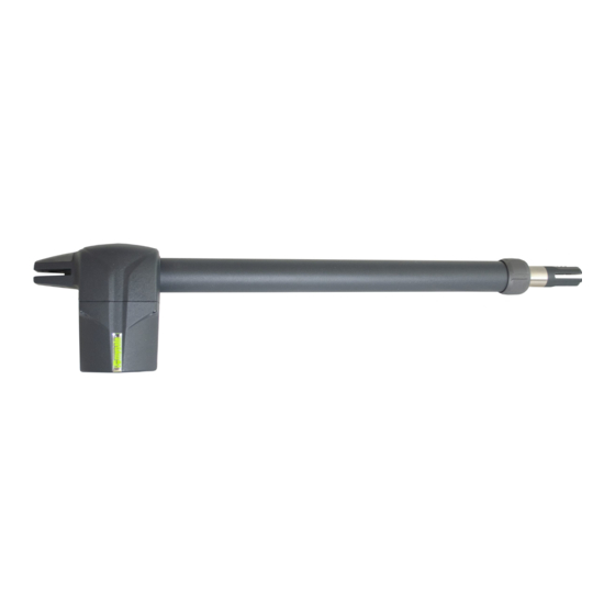
Summary of Contents for MyGate MYASTER NEW
- Page 1 Installation manual MYASTER NEW Automation for swing gates...
-
Page 3: Table Of Contents
Contents WARNINGS ................................ page INTENDED USE AND APPLICATION ........................page 01 ..........................Kit contents page ........................Technical data page Operator dimensions ......................... page INSTALLATION ............................page Preliminary checks ............................page Tools and materials (not included) ......................page Wiring installation overview ........................ -
Page 4: Warnings
WARNINGS This manual contains important information concerning personal safety. An incorrect installation or an improper use may lead to severe injuries. Read carefully and store for future use. Pay particular attention to this symbol Connect the automation to the earth system, which must be efficient and properly carried out. The installation of automatic doors and gates must comply with the Machine Directive 2006/42/CE, in particular EN 12453 and performed by qualified personnel only. -
Page 5: Technical Data
TECHNICAL DATA MYASTER 3 NEW MYASTER 4 NEW MYASTER 5 NEW MYASTER 6 24Vdc 230V-50Hz 115V-60Hz 24Vdc 230V-50Hz 24Vdc 230V-50Hz 230V-50Hz Power supply 115V-60Hz 115V-60Hz 0,75 0,75 0,75 Max. motor voltage Rated power µF Capacitor Thermal cut off C° 150° 150°... -
Page 6: Tools And Materials (Not Included)
TOOLS AND MATERIALS (NOT INCLUDED) PILLARS AND WALLS stainless steel concrete brick inox/alu. tubular Ø 15mm Ø 18mm LEAF wood stainless steel/alu 2 +2 rev01_22... -
Page 7: Wiring Installation Overview
WIRING INSTALLATION OVERVIEW pic. A ELENCO CAVI PER I VARI DISPOSITIVI 230V/115V 3 x 1,5 mm² + Terra Operator 2 x 1,5 mm² 2 x 1,5 mm² + Terra Control unit 2 x 1,5 mm² + Terra 4 x 0,5 mm² 4 x 0,5 mm²... -
Page 8: Installing The Operator
INSTALLING THE OPERATOR Check the orientation of the motors, left or right hand, referring to picture A. If hinges are positioned on the right (property view), the motor will be right hand, and viceversa. Make sure the gate is fitted with ground stops both in opening and closing (picture C). B = ground stops LH OPERATOR RH OPERATOR... - Page 9 3.3.2. CONSIGLI PER L’INSTALLAZIONE combinations according to the width of the pillar. Values are expressed in mm. MYASTER NEW can replace the previous model ensuring the same excursions Tutti i collegamenti devono essere effettuati in assenza d’alimentazione. and the same opening angles, without having to replace the existing ones.
-
Page 10: Outward Opening
3.4.3. OUTWARD OPENING It's possible to have your gate opening outward (picture F/G/H) 5 mm 5 mm pic.F pic.G 30 mm 5 mm pic.H MYASTER 3 NEW MYASTER 4 NEW MYASTER 5 NEW MYASTER 6 NEW Distance from pillar Bracket Min. -
Page 11: Fixing The Pillar Bracket
3.4.4. FIXING THE PILLAR BRACKET In order to properly cut the bracket start 12 mm from the hole center, as shown in the picture I. Fix the motor to the bracket following the below procedure: Linea di taglio pic.I pic.L •... -
Page 12: Fixing The Gate Bracket
3.4.5. FIXING THE GATE BRACKET Follow the below procedure to determine the bracket position on the gate: • Put the gate to CLOSING position. • Unlock the operator (refer to section 4 Manual Operation). • Extend the inox arm fully. •... -
Page 13: Wirings
3.4.6. WIRINGS Attention! An incorrect wiring could lead to failures and very dangerous injuries. Therefore carefully follow the wiring instructions contained in this manual. Switch the power and batteries OFF before any wiring operation. The electric plant must be performed by qualified personnel and must comply with the outstanding regulations. -
Page 14: Manual Release
MANUAL RELEASE • Switch the POWER OFF. • Lift the plastic cap acting on the right side of the operator (picture U). • Plug the release key and turn it 180° counter clockwise as shown in picture V. • The operator is now unlocked, manually open and close the gate. •... -
Page 15: Maintenance
MAINTENANCE ATTENTION! Maintenance service must be carried out by qualified technical personnel, in full compliance with the safety standards required by the laws in force. Maintenance has to be carried out every six months. In order to proceed to maintenance service, follow the below checks: •... -
Page 16: Compliance Declaration Ce
COMPLIANCE DECLARATION Manifacturer: PROTECO S.r.l. Address: Via Neive, 77 - 12050 CASTAGNITO (CN) - ITALY declares that: The product type: Automation for swing gates MYASTER MYASTER 3 NEW, MYASTER 4 NEW, MYASTER 5 NEW, MYASTER 6 NEW, Models: MYASTER 3 24 NEW, MYASTER 4 24 NEW, MYASTER 5 24 NEW, MYASTER 3 115 NEW, MYASTER 4 115 NEW, MYASTER 5 115 NEW. - Page 17 Via Neive, 77 - 12050 CASTAGNITO (CN) ITALY Tel. +39 0173 210132 mygateautomation.com info@mygateautomation.com...


Need help?
Do you have a question about the MYASTER NEW and is the answer not in the manual?
Questions and answers