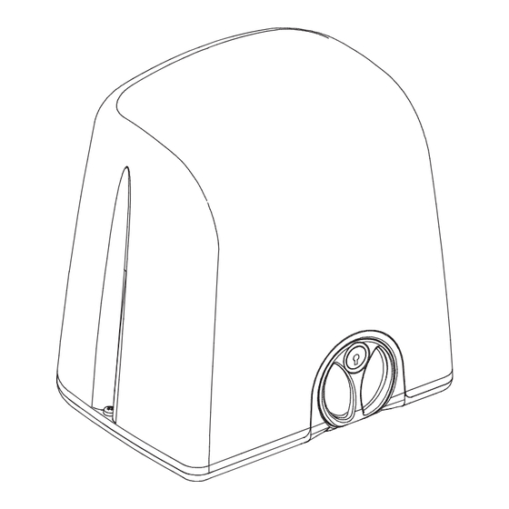
Table of Contents
Advertisement
Advertisement
Table of Contents

Summary of Contents for MyGate strike
- Page 1 Installation manual English STRIKE OPENER FOR RACK-DRIVEN SLIDING MOTOR...
-
Page 2: Ce Compliance Declaration
In case of a power failure the motor lock can be released to move the gate manually (see section 6). The STRIKE 4 version, 24 Volts, can also be powered by a back-up battery system that allows emergency openings even in case of a power cut. -
Page 3: Technical Specifications
ENGLISH 2.1 TECHNICAL SPECIFICATIONS STRIKE 5 STRIKE 8 STRIKE 4 STRIKE 5 110V STRIKE 8 110V 230V ~ 50Hz 230V ~ 50Hz 24Vdc 110V ~ 60Hz 110V ~ 60Hz Power supply 1,2 - 1,7A 1,2 - 2A 0,7 - 10A... -
Page 4: Electrical Cables Specifications
ENGLISH INSTALLATION 3.1 PRELIMINARY CHECKS Before the installation, to ensure correct working of the automation, please check the followings: • Make sure the gate’s structure is suitable to be automated • Check the weight, dimensions and type of the gate is appropriate to this type of automation •... -
Page 5: Tools Needed
ENGLISH 3.3 TOOLS NEEDED Fig. 2 3.4 PRELIMINARY INSTALLATION WORK AND MASONRY FOR ANCHOR PLATE Identify approximately the place of each component and proceed as follows: a) Dig the foundation pit for the gear motor whilst considering the anchor plate dimensions. Give an extra 5cm area extra on each side. -
Page 6: Installation Of The Gear Motor
ENGLISH Fig. 4 3.5 INSTALLATION OF THE GEAR MOTOR a) Lift up the motor cover. b) Insert the four hexagon-headed screws with the washers and nuts in the loops of the motor base (Fig. 4). c) Route the electrical cables in the purpose fabricated hole of the motor base (Fig. - Page 7 ENGLISH e) Keep the rack perfectly flat and fix it to the gate. Fig. 7a f) Repeat the same procedure until the gate is fully covered. g) In case the last section of rack partially comes out from the rack edge, do not cut it. Add a bracket as a gate extension to support the last bit of rack (Fig.
-
Page 8: Universal Steel Brackets
ENGLISH 3.7.1 PVC BRACKETS FOR TOOTHED RACK B117 Fig. 12 a) Identify closing and opening brackets according to the motor position against the gate (Fig. 12). b) Manually close the gate up to 3cm before the closing CLOSING OPENING mechanical stop. limit-switch limit-switch c) Place the closing bracket on the rack and slide it until the... -
Page 9: Electrical Wiring
ENGLISH RIGHT motor OPENING limit-switch LEFT motor CLOSING limit-switch Fig. 13 Fig. 14 Click! Click! Once the assembling of the limit brackets to rack is completed, open and close the gate manually to check that the brackets always activate the limit-switch system before the gate reach its mechanical stops. This checking is important to preserve the correct working of the automation and continued good mechanical condition of the gate. -
Page 10: Release Procedure For Manual Operation
ENGLISH 6. RELEASE PROCEDURE FOR MANUAL OPERATION Always cut the main power of the system during the release and re-locking procedure to avoid any accidental activa- Fig. 19 tion of the gate. 6.1 How to unlock the motor for manual opera- ting a) Insert the key into the lock and turn it anti-clockwise (Fig.


Need help?
Do you have a question about the strike and is the answer not in the manual?
Questions and answers