Table of Contents
Advertisement
Quick Links
Advertisement
Table of Contents

Related Manuals for MYPV ClearSky


Summary of Contents for MYPV ClearSky
- Page 1 ClearSky™ User Manual myPV ClearSky™ User Manual...
- Page 2 Welcome This interactive manual guides new and experienced users through the myPV ClearSky modular interconnection. Additional support is available on our website at www.myPV.pro You may also contact support via phone or email: Support Line (M-F, 9am-5pm Eastern): 470-387-9011 Support Email: operations@solar-ops.com...
- Page 3 Standard Options Standard Options Include 2021 Product Line Modifications Equipment Build Standards All myPV ClearSky equipment is built with quality and reliability as our top priority. Built to Last With heavy 11-gauge powder coated steel, wide temperature industrial rated electronics, and fully integrated in a UL...
-
Page 4: Standard Features
UL 508a certified and labeled Standard Features The myPV ClearSky Interconnection product line is designed to provide a self-contained and modularized solution for both distribution and transmission interconnected generation facilities operating up to 35kV with a maximum continuous current of 600A (per MV feeder). -
Page 5: Standard Options
In the event of loss-of-grid, the system remains fully operational to provide telemetry, trip event information and alarming. IEEE 386 MV Interfaces All configurations of the myPV ClearSky use industry standard bushing well and inserts MV interfaces. 200A load-break or 600A dead- break interfaces may be specified at the time of ordering based on facility amperage requirements. - Page 6 [OPTION] *Taller 12” riser (Adds an additional 5” of height for MV cable management) Solar-Side 3-Pole Ganged Load-Break Disconnect [DEFAULT] Not included[OPTION] **Manually operated. 600A load-break, 3-pole ganged disconnect (to isolate the myPV ClearSky™ fro the facility) Control Cabinet [DEFAULT] Technician visible wire-glass control cabinet door with external LOTO...
- Page 7 Contact Us for specifics myPV IQ™ - Remote Interface [DEFAULT] Installed and licensed for monitoring and control of the myPV ClearSky’s integrated metering and relaying devices [OPTION] Upgrade the myPV IQ license to support full facility device (inverters, trackers, weather stations, other) monitoring and control as the primary SCADA system.
- Page 8 Metering and Relaying CTs are now clearly labeled for both phase and orientation in the event they are unmounted during MV cable management The myPV IQ™ - Remote Interface and integrated cellular modem have been added to the standard product offering to support remote commissioning and troubleshooting by Customers, Customer assign Engineering resources, and Solar- Ops support staff.
-
Page 9: Technical Documents
Also referred to as “Elbows”, separable connectors are medium voltage (MV) components that provide a watertight, fully electrically insulated, electrical termination for MV conductors on both the Utility and Solar sides of the myPV ClearSky. All MV separable connectors support IEEE 386 compliant interfaces. - Page 10 3M - Separable Connectors [PDF] Product Line Specifications The myPV ClearSky product line is available in three (3) frame sizes that are determined by maximum voltage rating. A standard set of options may be added to any of the frame sizes to configure the standard product to meet individual customer requirements.
- Page 11 ClearSky™ 2021 - Product Line Representative Cross Section For myPV ClearSky™ products that have selected to add the option of a Solar-Side 3- Pole Ganged Load-Break Disconnect the following specifications should be used instead: Resources...
- Page 12 Resources...
-
Page 13: Product Photos
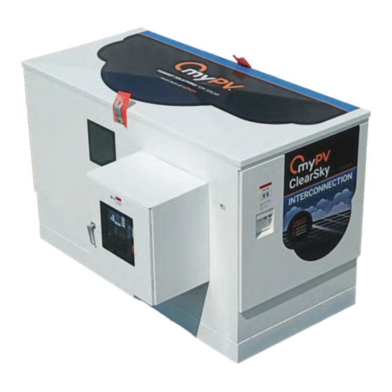
Product Photos While myPV ClearSky products do vary in size, all product frame sizes are arrange in the same manner. The following orthographic photos provide a visual reference for common locations of common features. Resources... - Page 14 Resources...
- Page 15 Frame Size by Voltage Class myPV ClearSky is available in three (3) frame sizes that are determined by the facility’s line-to-line voltage rating. Applications that have interconnection voltages equal to or below 35kV (line-to-line) are supported. Determine Your Facility’s Voltage Class:...
- Page 16 Potential Transformers (PTs) and Current Transformers (CTs) are devices used to measure voltage and current respectively. The myPV ClearSky has a single set of three (3) revenue grade PTs that are shared for metering and protection relaying functions. A fourth control power PT is used for control power (discussed in Design Considerations).
- Page 17 The protection CTs are specified to provide operation on the higher end of expected current flow to accurately capture (over current) fault events. NOTE: A fourth CT can be used to directly measure neutral current, however most meters and relays are capable of accurately calculating neutral current without a physical CT being installed.
- Page 18 The selection of instrument transformers is specific to the application, the interconnection and facility electrical characteristics, and also an Engineer’s preference. For the myPV ClearSky™, we have assembled the following table of standard part numbers for PTs and CTs to use, unless otherwise specified buy the Customer:...
- Page 19 Resources...
- Page 20 Resources...
-
Page 21: Design Considerations
ClearSky at the Point of Interconnection (POI). If you have concerns about the location of the myPV ClearSky’s metering and the POI, we recommend one of the following 2 approaches:... - Page 22 ClearSky Mechanical drawings. Foundation Type The myPV ClearSky requires a smooth, flat, horizontal surface to be mounted on that is appropriately designed to support its weight and footprint. Common foundations include, but are not limited to:...
-
Page 23: Electrical Isolation
(PT), the myPV ClearSky is self-powered. The control power PT is tapped to the Utility side MV bus, and will remain powered even when the internal MV VFI breaker is OPEN, ensuring the ClearSky never looses power while the grid is present. - Page 24 Both the power supply and UPS are wired to the protection relay alarming contacts to support fail-safe tripping logic. Network Cable Entry On the inside wall of the myPV ClearSky’s Utility Termination Cabinet, a dedicated wire gland has been installed to allow for network cable passthrough to the Control Cabinet network switch.
- Page 25 Protection Relay Settings The myPV ClearSky™ Interconnection is designed to provide a set of features that support witness testing requirements, maintenance modes, and protection requirements. Template Relay Settings File The SEL-751 Protection Relay, and the myPV ClearSky’s intended operational behaviors rely on logic programmed into the relay’s RDB settings file.
- Page 26 Only by pushbutton, the Protection Relay can 1-Phase CLOSE Power Supply & UPS Battery TRIP The myPV ClearSky’s SEL-751 is pre-programmed to support TRIP on-alarm- condition for the following conditions and time delays: On loss-of-control-power, when the N.O. power supply digital output OPENs, the Protection Relay will TRIP after 30 seconds.
- Page 27 Both time delays may be adjusted to support longer or shorter durations by modifying the RDB template settings file. Single-Phase TRIP Support The myPV ClearSky’s SEL-751 is pre-programmed to support both 3-Phase and 1- Phase TRIP support functionality. I-Phase TRIP support may be used by commissioning staff validate proper inverter anti-islanding behaviors, as required by IEEE 1547.
- Page 28 To change or verify shipping schedule and details please contact your Solar-Ops Account Manager. Arrival The customer is responsible for receiving and unloading of all equipment deliveries. The myPV ClearSky will arrive to your shipping address location palletized, on an open flat bed truck. Receiving...
- Page 29 Whenever possible, your Solar-Ops Account Manager will share tracking information and put the driver directly in contact with the receiving party for receiving coordination. All equipment arrives palletized, and may be lifted using the pallet for initial unloading. The equipment arrives with four (4) SS Strap Clamps… DO NOT DISCARD THE SS STRAP CLAMPS.
-
Page 30: Lifting & Handling
The myPV ClearSky arrives with two (2) lifting eyes installed on the Front and Back side walls of the device to facilitate use of a spreader bar or chain. - Page 31 Setting & Orientation The myPV ClearSky should always be set on level, flat, and solid foundation that is properly designed to support its weight and size. The myPV ClearSky has two electrical termination cabinets that are specific to the “Utility Side” and “Solar Side” medium voltage (MV) conduit locations.
- Page 32 Securing The myPV ClearSky is designed to be secured to the foundation using four (4) SS Strap Clamps (included) and secured with one (1) SS 1/2” diameter threaded stud with nut and washer set (4 sets total, not included). All four (4) nuts should be tightened in accordance with the Torque Schedule and threaded stud specification.
- Page 33 Zip Tie Removal For shipping, zip ties are installed around the four (4) potential transformer (PT) fuses inside the center switching cabinet. The zip ties are installed to ensure the fuses do not come loose during shipping and need to be removed. The PTs may be most easily accessed prior to any medium voltage (MV) conductors being pulled into the MV Termination cabinets.
- Page 34 The myPV ClearSky™ Interconnection is designed to electrically terminate in the same manner as a pad-mounted transformer. Here’s what you can expect. Overview The myPV ClearSky is designed to be very easy to install, requiring only medium voltage (MV) and ground-ring terminations that are similar to that of a pad-mount transformer.
- Page 35 Utility Side MV Terminations All metering and protection relay current measurements are measured from the Utility side of the myPV ClearSky. To ensure the current transformers (CTs) are easily serviceable, all six (6) CTs are installed outside the central switching cabinet.
- Page 36 All Solar side terminations are identical to the Utility side, with one large exception … the A, B, C phasing is in reverse: C, B, A from left-to-right. The myPV ClearSky uses bus bars that pass from the Utility side to the Solar side, thought the central switching cabinet, and never cross.
-
Page 37: Conduit Entries
Conduit Entries All conduits should be adequately sealed to prevent the ingress of water, moisture, and hazardous gases into the MV termination cabinet. Sealed MV Conduit Electrical Terminations... -
Page 38: Network Integration
ClearSky™ Interconnection is intended to be a first class “Connected Plant” device. Overview The myPV ClearSky may be added to the local area (LAN) Facility network via an integrated network switch. All internal networkable devices are connected to that central switch and may be accessed via MODBUS TCP/IP, Web-Hosted Interface, or Vendor Provided Software. - Page 39 Communications conduits should be run in parallel to the medium voltage (MV) cable conduits, and located inside the Utility Side MV Termination Cabinet. A dedicated large-bore (1-1/2” Diameter) wire gland is located on the left side wall of the Utility Side MV Termination Cabinet, labeled “NETWORK” to allow media routing between termination cabinet and the Control Cabinet.
- Page 40 Ethernet and/or fiber media will need to be terminated and tested by the installer, and connected to the network switch inside the Control Cabinet. Device Communications The myPV ClearSky supports multiple communication options for all networkable devices the support: third-part monitoring, SCADA, and even IT reporting requirements. Communications Options:...
-
Page 41: Pre-Energization Checks
(MV) and/or auxiliary (e.g. generator) power sources. It is strongly recommend that a LOTO’d air-gap isolation plan be established on both the Utility side and Solar side of the myPV ClearSky device, using air-gap visible OPEN devices that are OUTSIDE the myPV ClearSky™ device. -
Page 42: Grounding Verification
Multimeter w/ resistance (Ω) testing Grounding Verification It is important that the myPV ClearSky be properly grounded to prevent any transient voltages from not having a safe path to ground. Due to the myPV ClearSky’s location on an equipment pad and grounding ring, Solar- Ops recommends the maximum ohmic resistance between the device grounding rod and the associated ground will be <... - Page 43 MV Termination Verification On both the Utility Side and Solar Side, all six (6) MV elbows should be be fully seated on the inserts. 200A load-break connections are pushed on until the are fully seated and no “color ring” is visible. 600A dead-break connections (e.g.
- Page 44 VFI Breaker Position Verification The myPV ClearSky has three (3) independent MV VFI Breakers that provide protection isolation, reclosing, and can support single-phase drop testing as well. All three (3) breaker’s positions should be visually verified to ensure they are in the OPEN (indicate GREEN) position.
- Page 45 CT Orientation & Wiring Verification Metering & protection relaying functions require proper orientation and location of all six (6) CTs. A flipped CT will report current for that phase importing rather than exporting. A CT located on the wrong phase will not properly align with voltage for the same phase and provide inaccurate measurements.
- Page 46 PT Fuse Verification Inside the center switching cabinet, four (4) fused PTs may be observed using the two (2) external wire-glass windows. Visually verify all four (4) PT fuses are intact. A fuse that is “indicating” (see example image) is not longer intact and will require replacement prior to operation. Pre-Energization Checks...
-
Page 47: Control Panel Preparation
Control Panel Preparation Prior to energization, preparation of the Control Panel is intended to prevent damage to the electrical components due to out-of-range source voltages and also stages the Control Panel for commissioning steps that will be taken in the next section Initial Energization. - Page 48 Control Panel Verification Locations Pre-Energization Checks...
- Page 49 Reference the image number callouts for additional verification locations: 1. Perform a gentle control wiring pull test of the AC control power terminations 2. Perform a gentle control wiring pull test of the PT, CT, and VFI Breaker position terminations Control Panel Wiring Pull Test Locations Finally, switch the Control Panel Mode Selector into Repair Service Mode.
-
Page 50: Initial Energization
Pre-Energization Checks. If you have not yet performed the Pre-Energization Checks, or have taken any actions that altered the as-left conditions of the myPV ClearSky set forth at the completion of the Pre-Energization Checks, we strongly recommend performing the Pre-Energization Checks before proceeding. - Page 51 A review of on-site and local emergency response resources, including: fire extinguishers, first aide kits, first responders, hospitals, police, fire, and EMS. myPV ClearSky Commissioning Tools & PPE Required: 1. Multimeter (120V AC RMS and 24V DC Capable Readings) 2.
- Page 52 2. Phase-C identification from Interconnection, through the test-switches, to the Meter & Protective Relay For the following steps, the myPV ClearSky’s Control Panel door will beed to be open’d and the dead front swung open to allow for AC power measures.
- Page 53 3. If [PASS] where ~120V AC is present In both locations: a. CLOSE the 3-pole fuse block (energizing PT references up to the control back panel fuses) b. CLOSE the 2-pole breaker (energizing the space heater circuit & the controls back panel 001 fuse) Control Power Commissioning Verify proper AC and DC voltages prior to energizing controls equipment.
- Page 54 ◦ Hub-E8 - Network Switch (Based on Customer options, there may be additional devices) ◦ RV50 - Cellular Modem ◦ myPV-IQ - Edge Computer for myPV IQ™ - Remote Interface ◦ BRKR-A - Phase-A Tavrida VFI Control Module ◦ BRKR-B - Phase-B Tavrida VFI Control Module ◦...
- Page 55 Initial Energization...
- Page 56 Phase-A & Phase-B Energization With phase-C previously energized, and the Controls Cabinet powered, phase-A and phase-B may now be energized. Commissioning Steps: 1. Verify phase-C voltage by using a Multimeter (set to AC RMS) to verify the presence of ~120V AC voltage (±10%, 108 - 132V) at locations (C) 602 a.
- Page 57 Fused PT References Shown OPEN, for Voltage Testing With all three (3) fused PT references closed, the following verifications may be made using the SEL-735 Meter and SEL-751 Protection Relay: L-L interconnection voltages If L-L (or L-N) voltages are not within the expected interconnection ranges, verify the PTR and CTR settings in the SEL-735 Meter and SEL-751 Protection Relay Frequency...
-
Page 58: Operational Testing
If you have not yet performed the Initial Energization, or have taken any actions that altered the as-left conditions of the myPV ClearSky set forth at the completion of the Initial Energization, we strongly recommend performing the Initial Energization before proceeding. - Page 59 3. Verify the TRIP button’s BREAKER OPEN Green Indication is illuminated 4. Verify the SPD-TEST button’s DISPABLE Yellow Indication is illuminated Numbered Illustration of Mode Selection Switch & Protective Relay Indicators Manual 3-Phase Operation While still in REPAIR SERVICE MODE, the MV VFI Breakers may be cycled OPEN and CLOSE independent of any protection logic or recloser settings.
- Page 60 Numbered Illustration of Protective Relay Indicators Testing 1-Phase Operation In support of IEEE 1547 loss-of-phase testing requirement, the myPV ClearSky has been designed to support pushbutton-single-phase-testing capabilities. Single phase testing is a special mode that must be enabled by the Commissioning...
- Page 61 MODE. Single Phase Test Operation: 1. Press and Hold the SPD-TEST button for approximately 5 seconds, until … 2. … the ENABLED Yellow indicator is illuminated 3. Firmly press the A-PHASE button to TRIP the MV VFI Breaker for phase A … the breaker should TRIP / OPEN 4.
- Page 62 At any time a single-phase is OPEN, rotating the Selector Mode Switch to AUTOMATIC will enable protection logic and force a 3-phase TRIP condition Commercial Operation Following testing, take the following steps, once you are ready to place the myPV ClearSky™ into normal commercial operation. Commercial Operation Settings: 1.
- Page 63 The myPV ClearSky may be left in this condition indefinitely. Operational Testing...
- Page 64 Numbered Illustration of Mode Selection Switch & Protective Relay Indicators Operational Testing...
- Page 65 Facility. Recommended Maintenance Schedule The myPV ClearSky is designed to be maintenance free, and requires no regular consumables or maintenance service under normal operational conditions. The following table established recommended inspection frequency for preventative maintenance scheduling.
- Page 66 Every Description Inspection Outage (Yrs) Following isolation and LOTO, the Utility side MV Termination cabinet should be opened to: 1. Inspect that it is free of debris, water, animals, or other contamination 2. MV elbows are firmly seated 3. MV conductors are fee of defects 4. All grounds and bleed wires are intact 5.
-
Page 67: Spare Parts
Spare Parts The myPV ClearSky is designed with high quality, industrial grade, components that are intended to provide reliable operation throughout the commercial operating lifespan of your facility. Having a complement of spare parts on-hand however can prevent unnecessary prolonged downtimes. - Page 68 Spare Parts...
- Page 69 Spare Parts...
- Page 70 Torque Schedules The myPV ClearSky™ Interconnection was designed to be mechanically assembled using the following torque schedules. Torquing Values For all bolted connections, unless otherwise specified, refers to the chart below. For electrical components, see component manufacturer’s data for all screw terminal tightening torques.
-
Page 71: Troubleshooting
Troubleshooting Eliminate the most common myPV ClearSky™ Interconnection operational issues quickly and safely. Missing Single-Phase Current Whether in the SLE-735 Power Quality Meter, or the SLE-751 Protection Relay, a zero value (0.0A reading) is most commonly due to a CT wire lead being terminated improperly in the Utility MV Termination Cabinet. - Page 72 MV Breaker Will Not CLOSE Following a TRIP event, the Protection Relay will not allow a CLOSE command if the TRIP has net been cleared. An uncleared TRIP event will cause the Red TRIP indicator to illuminate. To clear the TRIP event, press the TARGET RESET until the Red TRIP indicator is no longer illuminated.
Need help?
Do you have a question about the ClearSky and is the answer not in the manual?
Questions and answers