
Related Manuals for Allied Leister GEOSTAR G5 LQS

Summary of Contents for Allied Leister GEOSTAR G5 LQS
- Page 1 English GEOSTAR G5 LQS / G5 G7 LQS / G7 Leister Technologies AG Galileo-Strasse 10 6056 Kaegiswil Switzerland +41 41 662 74 74 leister@leister.com www.leister.com...
-
Page 2: Table Of Contents
Table of contents 1. Use 1.1 Intended use 1.2 Non-intended use 2. Important safety instructions 3. Technical data 4. Transport 5. Device description 5.1 Overview of device parts 5.2 Operating unit 5.3 Status LED display “Heating” 5.4 Status LED display “Drive” 5.5 Operating unit description 5.6 Display description 5.7 Function and working display... -
Page 3: Use
Operating instructions (translation of original operating instructions) We congratulate you on the purchase of a GEOSTAR wedge welder. You have selected a first-class wedge welder comprised of high-quality materials. This device was developed and produced in accordance with the latest welding technologies. Every GEOSTAR is subjected to strict quality monitor- ing before it leaves the factory in Switzerland. -
Page 4: Important Safety Instructions
2. Important safety instructions Warning Danger to life There is a danger to life from electric shock due to electrical voltage. The hot wedge welding machine must therefore only be connected to sockets and extension cables with a protective earth conductor. Protect the hot wedge welding machine from moisture and wet conditions. -
Page 5: Technical Data
3. Technical data GEOSTAR G5 LQS GEOSTAR G7 LQS Device model GEOSTAR G5 GEOSTAR G7 * Voltage 220 – 240 220 – 240 Power 2800 2800 Frequency 50 / 60 50 / 60 Temperature, stepless °C 80 – 460 80 – 460 °F 176 –... -
Page 6: Device Description
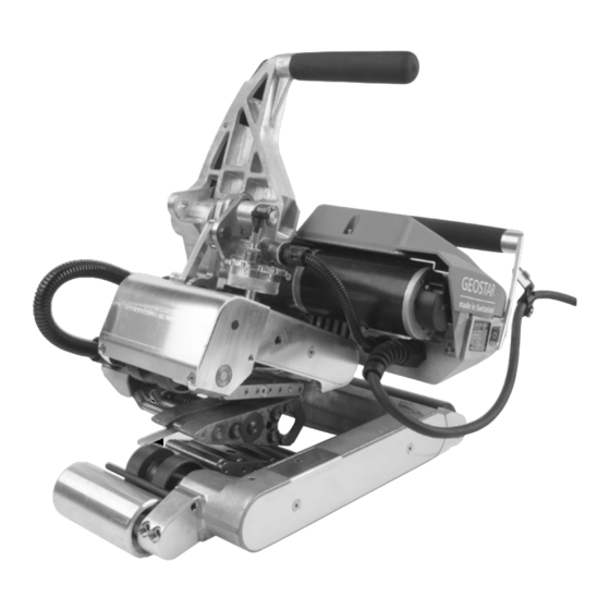
5. Device description 5.1 Overview of device parts 1. Power supply cord 12. Track roller, rear 2. Main switch 13. Welding wedge plug 3. Operating unit 14. Contacting system, upper 4. Clamping arm 15. Contacting system, lower 5. Welding wedge 16. -
Page 7: Operating Unit
5.2 Operating unit 27. “Up” key 28. “Down” key 29. Key for heating “On/Off” 30. Key for drive “On/Off” 31. Status LED 32. «e-Drive» 33. Function display 34. Working display 35. Status display “Section 1” 36. Status display “Section 2” 5.3 Status LED display “Heating”... -
Page 8: Status Led Display "Drive
5.4 Status LED display “Drive” The LED of the Drive “On/Off” key (30) shows the condition of the drive when it is working as intended. LED status (31) Condition Cause Drive On/Off (30) LED off Drive is switched off. LED continuously green Drive is switched on. -
Page 9: Display Description
5.6 Display description Status display “Section 1” (35) Name of the Profile currently selected. If profile names consist of more than 6 characters, the first saved value 6 characters are shown first, followed by the remaining characters. 230 V Network voltage currently present on the mains plug. Status display “Section 2”... - Page 10 Working display (34) Symbol Meaning Drive speed [m/min / ft./min] Drive speed blocked [m/min / ft./min] Welding wedge temperature [°C/°F] Welding force [N/lbf] Information box Devices in standby mode. The heating is switched off after the counter runs through. An error has occurred. An error code also appears (the device is no longer ready for use).
- Page 11 Startup display Recipe selection Display at the time of start- Select a recipe that you up with software release have defined. The process and device model. of selecting a recipe is described in detail in the Chapter “Load recipes”. Maintenance service Setting In the basic setting, you If the maintenance interval...
- Page 12 Readiness Show Duty Info Standby mode is activated. Hours Drive: If the engine is switched Current running time off, the heating activated of the drive and if no button is ac- Hours Heating: tivated during the time Current running time defined under “Standby of the heater interval”, then the device...
- Page 13 Machine Setup Set Values If “Set Values” is activated, Unit: both the actual values and Adjusting the unit used the set values are displayed (metric/imperial) in small font size. Unit Speed: Factory setting activated. Adjusting the LCD contrast Unit Heat: Adjusting the background Reset to defaults illumination of the display...
-
Page 14: Menu Navigation
6. Menu navigation The GEOSTAR G5 LQS and GEOSTAR G7 LQS have the Leister Quality System (LQS) and thus the function of welding data recording. Using the LQS and myLeister app, the drive speed, the hot-wedge temperature and the joining force are recorded during welding over the welding seam length at the specified distance interval. -
Page 15: Work Environment/Safety
7. Work environment/Safety The device should only be used in the open or in a well-ventilated area. Be careful not to burn the material during welding. Read and follow the safety precautions provided by the manufacturer for the material. Prior to commissioning, check the power supply cord (1), the plug, and the extension cable for electrical and mechanical damage. -
Page 16: Setting The Welding Parameters
8. Setting the welding parameters CAUTION! The welding wedge is set to 2 mm membranes in the factory settings. The welding wedge (5) must be cooled down for adjustment purposes. Danger of crushing when closing the clamping arm (4). Switch off GEOSTAR with the main switch (2) and disconnect from the mains. Welding force and contacting system A. - Page 17 C. Insert test strips (lower and upper membranes) of the material to be welded between the upper and lower drive/ pressure rollers (16/17) and between the upper and lower contacting systems (14/15) and welding wedge (5). Press the locking clamping lever (10) and close the clamping arm (4) using the clamping lever (7). Use your other hand to accomplish this by holding the automatic welder firmly by the handle (11).
- Page 18 E. Switch off the main switch (2) and disconnect GEOSTAR from the mains. While clamped, screw the lower contacting system (15) with the lower contacting system setting screw (19) in the direction of the welding wedge (5) until the lower test strip is touching the welding wedge (5). Then rotate the lower contacting system setting screw (19) once in the direction of the welding wedge (5) so that the upper contacting system (14) is pre-tensioned.
-
Page 19: Function Description
8.1 Function description Heating system: • The welding wedge temperature is adjustable and electronically controlled between 80 °C and 460 °C. • The temperature can be set in 5 °C increments. Welding force • The welding force is steplessly adjustable. The welding force is transmitted through the clamping lever (7) and clamping arm (4) to the upper and lower drive/pressure rollers (16/17). -
Page 20: Setting The Speed And Temperature During Welding
8.3 Setting the speed and temperature during welding If the drive is switched on, then the temperature and speed welding parameters in the working display (34) are set as follows: • The speed working display (34) is blocked during welding. •... -
Page 21: Starting The Device
8.4 Starting the device • If necessary, mount the respective drive/pressure rollers (16/17) and set the desired transmission ratio (see Chapter “Change gear speed”). Before starting the device, check the power cord, the plug and the extension cable for electrical and mechanical damage. -
Page 22: Welding Process
8.5 Welding process Before the wedge welder is used, test welds are to be carried out in accordance with the welding instructions of the material manufacturer and with national standards or guidelines. The test welds must be checked. • The wedge welder temperature must be achieved. •... -
Page 23: Display Of Day's Distance
8.7 Display of day's distance The welded distance is recorded as soon as the drive is running and more than 100 N force is displayed in the working display (34). The day's distance can be called up as follows: Not in welding mode •... -
Page 24: Deleting The Day's Distance
8.8 Deleting the day's distance • In the function display (33), rotate the «e-Drive» to select the Settings menu. • Press the «e-Drive» briefly. • Select “Duty Info” in the “Setup” menu by rotating the «e-Drive» and pressing it briefly •... -
Page 25: Entering Names Or Passwords
8.11 Entering names or passwords In keyboard mode, you can define names or enter passwords with a maximum of 12 characters. Keyboard Character selection (37) Symbol selection (38) Up (27) Vertical character selection Down (28) Rotate «e-Drive» (32) Horizontal character selection Horizontal symbol selection Press «e-Drive»... - Page 26 Creating a new recipe: • In the working display (34), set the desired setpoints with the «e-Drive» • In the function display (33), use the «e-Drive» to select the Settings menu and confirm this by press- ing the «e-Drive» • In the “Setup” menu, select the “Save recipe” option with the «e-Drive» and confirm by pressing the «e-Drive»...
-
Page 27: Power Supply Interruption
9. Power supply interruption Condition of device prior to mains Duration of power Condition of device after mains interruption supply interruption interruption The device continues running without Drive and heating are switched on (welding ≤ 5 sec. a restart safeguard with the same set- process). -
Page 28: Change Gear Speed
11. Change gear speed Gear speed slow Gear speed fast The machine has less feeding force (smaller torque) at the “fast” gear level. Risk of burning! Before dismantling, it must be ensured that the welding wedge has cooled down, the device has been switched off with the main switch (2), and the power cord is disconnected from the mains. - Page 29 D. Mount the transmission cover (43) with the countersunk screws (42). E. Adaptation of the transmission ratio • In the function display (33), use the «e-Drive» to select and then confirm & the setting • Afterwards, select “Gear Ratio Drive” by rotating the «e-Drive»...
-
Page 30: Replacement Of Pressure Rollers
12. Replacement of pressure rollers Risk of burning! Before dismantling, it must be ensured that the welding wedge has cooled down, the device has been switched off with the main switch (2), and the power cord is disconnected from the mains. Depending on the application, different drive/pressure rollers may be used. -
Page 31: Welding Wedge Replacement
13. Welding wedge replacement Risk of burning! Before dismantling, it must be ensured that the welding wedge has cooled down, the device has been switched off with the main switch (2), and the power cord is disconnected from the mains. A. -
Page 32: Warnings And Error Messages
14. Warnings and error messages • If there is a warning pending, the user can continue to work. You can access more detailed information about the warning via the function display (33) by selecting “Warnings” in the Settings menu. • If a warning occurs while welding, this can be displayed with the “Up” key •... -
Page 33: Accessories
15. Accessories • Only Leister accessories may be used. 16. Training course • Leister Technologies AG and its authorized service points offer welding courses and introductory training classes. Information at www.leister.com. 17. Maintenance Risk of burning! Do not touch the welding wedge when it is hot. Allow the device to cool down. -
Page 34: Conformity
19. Conformity EU Declaration of Conformity Leister Technologies AG, Galileo-Strasse 10, CH-6056 Kägiswil, Switzerland confirms that this product in the model made available for purchase, fulfills the requirements of the following EU directives. Directives: 2006/42/EC, 2014/30/EU, 2014/53/EU, 2011/65/EU Harmonized standards: EN ISO 12100, EN 55014-1, EN 55014-2, EN 61000-6-2, EN 61000-3-2, EN 61000-3-3, EN 62233, EN 60335-1, EN 60335-2-45, ETSI EN 300 328, EN IEC 63000... - Page 35 • Guarantee or warranty claims cannot be asserted for devices that have been converted or changed by the purchaser or for which non-original Leister spare parts have been used. Allied Power Tools 12/ 76 Rushdale St, Knoxfield VIC 3180 Australia T: + 61 3 9764 2911 E: sales@alliedpowertools.com.au...
Need help?
Do you have a question about the Leister GEOSTAR G5 LQS and is the answer not in the manual?
Questions and answers