Table of Contents
Advertisement
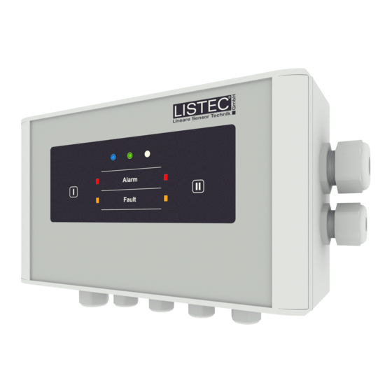
d-LIST
Sensor Control Unit SCU 835
Sensor Cable SEC 15
Valid as of:
Firmware version
V01.00.xx
Serial number
3382706176
LISTEC
and LIST
are registered trade marks
®
Line Type Heat
Detector
Instructions for use
LISTEC GmbH ▪ Am Sandberg 34 ▪ D-84424 Isen
Tel. +49 8083 5385-0 ▪ Fax +49 8083 5385-20
www.listec-gmbh.de ▪ info@listec-gmbh.de
A company of the Swiss Securitas Group
Advertisement
Table of Contents

Subscribe to Our Youtube Channel
Related Manuals for Listec d-LIST SCU 835

Summary of Contents for Listec d-LIST SCU 835
- Page 1 Serial number 3382706176 LISTEC and LIST are registered trade marks LISTEC GmbH ▪ Am Sandberg 34 ▪ D-84424 Isen Tel. +49 8083 5385-0 ▪ Fax +49 8083 5385-20 www.listec-gmbh.de ▪ info@listec-gmbh.de A company of the Swiss Securitas Group...
- Page 2 All rights reserved under copyright laws. No part of this manual may be duplicated, transferred to third parties, or used for other purposes than intended, without prior written consent of LISTEC GmbH. The German version is binding for technical documentation translations.
-
Page 3: Table Of Contents
Cable imprints............................31 4.1.5 Pre- and/or post-runs..........................31 4.1.6 Cut sensor element..........................32 Connection box CBO 15......................... 33 Connection cable CC 15......................... 36 End device END............................36 SCU 835..............................37 Sensor cable connections........................41 60T328-02-LI-en / 29.01.2021 LISTEC GmbH Page 3/112... - Page 4 J-clamp 1.4529 / mounting device MDJ 50..................... 79 11.5 Cable clamp MDC........................... 80 11.6 Cable tie FEMC............................80 11.7 Connection box CBO 15......................... 81 11.8 Connectors SECcon 15.......................... 82 11.9 External sensors ESD-A5........................83 Page 4/112 LISTEC GmbH 60T328-02-LI-en / 29.01.2021...
- Page 5 Alarm and pre-signal events SCU 835....................109 16.2 Sensor cable SEC 15 faults........................109 16.3 General device malfunctions SCU 835....................110 16.4 Status messages SCU 835........................110 Photo credits............................110 Abbreviations in this manual......................111 60T328-02-LI-en / 29.01.2021 LISTEC GmbH Page 5/112...
-
Page 6: Conventions
Swiss Securitas Group, division Special Fire Detector Technology. The serial numbers are in ascending order and can be freely assigned to the products up to the provisional final serial number 3383754751 devices, circuit boards, connection boxes etc. Page 6/112 LISTEC GmbH 60T328-02-LI-en / 29.01.2021... -
Page 7: Safety And General Information
… 104 °F)! This limit must be adhered to at all times in order to not damage the sensors inside the cable! Note A corresponding information is attached to each cable drum or cable ring (document no. F019). 60T328-02-LI-en / 29.01.2021 LISTEC GmbH Page 7/112... -
Page 8: Intended Use Of The Product
Table 1: Intended use Attention If the d-LIST system is not used for its intended purpose, there is no warranty and it contradicts the C Directives according to the Construction Products Regulation (EU) No. 305/2011 (EU-BauPVO). Page 8/112 LISTEC GmbH 60T328-02-LI-en / 29.01.2021... -
Page 9: Warranty
- secuted. Pictures and drawings are subject to the copyright of LISTEC GmbH, unless otherwise stated in the re- spective categories of these operating manual (→ 17). -
Page 10: Standards And Product Marking
The SCU 835 and various assemblies and accessories are provided with a type plate for easy identification. These are marked as follows: Sensor control unit SCU 835 Fig. 1: Type plate SCU 835 Connection box CBO 15 Fig. 2: Type plate CBO 15-SEC Page 10/112 LISTEC GmbH 60T328-02-LI-en / 29.01.2021... - Page 11 Fig. 4: Type plate mainboard MB SCU 835 (Replacement article for MB SCI 835) Fig. 5: Type plate mainboard MB SCI 835 Fig. 6: Type plate relay board REL 835 Fig. 7: Type plate universal connection module UCM 15-SEC 60T328-02-LI-en / 29.01.2021 LISTEC GmbH Page 11/112...
- Page 12 Relay board REL 835 Universal connection module UCM 15-SEC as well as UCM 15-ESD. Fig. 9: Type plate II secondary packing mainboard MB SCI 835 Fig. 10: Type plate II secondary packing relay board REL 835 Page 12/112 LISTEC GmbH 60T328-02-LI-en / 29.01.2021...
-
Page 13: Environmental Protection
Prefabrication SECcon 15 Sales document 60V184 Service case SC 15/20 Sales document 60V185 Sensor control unit SCU 835 Sales document 60V206 Connection box CBO 15 Sales document 60V212 Table 2: Further documentation – data sheets 60T328-02-LI-en / 29.01.2021 LISTEC GmbH Page 13/112... - Page 14 60T334 Operation Manual GUI d-LISTconfig Technical Document 60T340 Guidelines for planning and installation SCU 835 / Sales Document 60V219 sensor cable SEC 15 Table 5: Further documentation - manuals / protocols / instructions Page 14/112 LISTEC GmbH 60T328-02-LI-en / 29.01.2021...
-
Page 15: System Description And Function
No special tools are required for the installers to connect the sensor elements to a CBO 15 connection box or to connect them via SECcon 15 plug connector (→ 3.2.4, 5.5). 60T328-02-LI-en / 29.01.2021 LISTEC GmbH Page 15/112... -
Page 16: Standard Prefabrication Cbo 15 And Multiple Branching
For the following example applications with multiple branches: Further sub-branches are not possible! The maximum cable length is reduced with the number of branches (→ Examples). Fig. 14: Multiple branching: 2-times with max. 300 m per cable connection Page 16/112 LISTEC GmbH 60T328-02-LI-en / 29.01.2021... - Page 17 SCU 835 / SEC 15 Instructions for use Fig. 15: Multiple branching: 3-times with max. 260 m per cable connection 60T328-02-LI-en / 29.01.2021 LISTEC GmbH Page 17/112...
- Page 18 Instructions for use SCU 835 / SEC 15 Fig. 16: Multiple branching: 4-times with max. 220 m per cable connection Page 18/112 LISTEC GmbH 60T328-02-LI-en / 29.01.2021...
-
Page 19: Connection On Site
(→ 5.2). Important note When inserting the shield connector SCON 15/1 make sure that there is contact to the aluminium shield. A check with a multimeter is recommended (→ 5.3). 60T328-02-LI-en / 29.01.2021 LISTEC GmbH Page 19/112... -
Page 20: Maximum Cable Length
SEC 15/05 (5 m) 400 m (80 Sensors x m / Port (→ Note) SEC 15/10 (10 m) 640 m (64 Sensors) x m / Port (→ Note) Table 7: Sensor cable length in 2-channel operation Page 20/112 LISTEC GmbH 60T328-02-LI-en / 29.01.2021... -
Page 21: Prefabrication Via Connector Seccon 15
Simple replacement of sensor elements after damage is possible without special tools. Can be connected to cable port I and/or II of the device. Fig. 19: SECcon 15: variant 1 Fig. 20: SECcon 15: variant 2 60T328-02-LI-en / 29.01.2021 LISTEC GmbH Page 21/112... -
Page 22: External Sensors Esd-A5
200 m. In this case, a maximum of 100 sensors per cable connection I / II must be observed, whereby a maximum of four individual ESD-A5 sensors can be connected to each of the two cable ends. Page 22/112 LISTEC GmbH 60T328-02-LI-en / 29.01.2021... - Page 23 CC 15 and the lengths of the external sensor connection cables must be kept to 100 m per cable port I / II, with a total of up to 50 external sensors. Fig. 25: Variant without sensor cable SEC 15 60T328-02-LI-en / 29.01.2021 LISTEC GmbH Page 23/112...
-
Page 24: Operation Modes
The measuring cycle time for approx. 100 sensors per cable connection I and/or II is about five seconds. The two cable inputs are measured and evaluated in- dependently at the same time. Page 24/112 LISTEC GmbH 60T328-02-LI-en / 29.01.2021... -
Page 25: Evaluation Of The Temperature Values
2.5 K Maximum temperature threshold: 70.0 °C 85.0 °C Measuring cycle: 10 sec 10 sec Reference tracking: Table 9: Response classes BN, CN Note Changing any one parameter voids approval by VdS Schadenverhütung. 60T328-02-LI-en / 29.01.2021 LISTEC GmbH Page 25/112... -
Page 26: Reference Profile
Alarms can only be reset if the corresponding alarm criterion is no longer fulfilled. In other words, the cur- rent temperature value must be 20% below the set differential alarm threshold or 5% below the max- imum alarm threshold. Page 26/112 LISTEC GmbH 60T328-02-LI-en / 29.01.2021... -
Page 27: Fault Signalling
(→ 6.5). Optionally, a relay board REL 835 can be installed, with a maximum of 16 relays for alarm, pre signal or malfunction per fire zone (→ 6.12). Note All relay contacts of the SCU 835 and the relay board REL 835 are potential-free. 60T328-02-LI-en / 29.01.2021 LISTEC GmbH Page 27/112... -
Page 28: Optocoupler Outputs
Seconet BX-OI3 → 6.15.1, Honeywell/ESSER 808623 → 6.15.2 or Siemens FDCIO222 → 6.15.3). 3.21 Real time clock The sensor control unit SCU 835 has a real time clock RTC on the mainboard (→ 6.16). Generally the time is given in UTC (Coordinated Universal Time). Page 28/112 LISTEC GmbH 60T328-02-LI-en / 29.01.2021... -
Page 29: Installation
Furthermore the female crimp connector CLB 2 and the shield connector SCON 15/1 are located under the red ESD protection cap. Note Appropriate information is provided on each cable drum or cable ring (→ Document no. F019 resp. F091). In case of doubt contact your supplier! 60T328-02-LI-en / 29.01.2021 LISTEC GmbH Page 29/112... -
Page 30: Installation Of The Sensor Elements Sec 15
For high voltage lines ≥ 10 kV additional project information is required, such as: shielded / unshielded lines, common metal support, switching interference, expected currents and others. The national and normative regulations must be observed in any case. For project planning it is recommended to contact the manufacturer. Page 30/112 LISTEC GmbH 60T328-02-LI-en / 29.01.2021... -
Page 31: Cable Imprints
8 m, unless special partial lengths have been ordered (e.g. when a 2.400 m cable drum is delivered). The pre- and post-run does not contain any sensors and is not part of the specified partial lengths on the delivery note. 60T328-02-LI-en / 29.01.2021 LISTEC GmbH Page 31/112... -
Page 32: Cut Sensor Element
A cut through the sensor element between two sensor markings should always be done after half of the sensor spacing. Seal the end with an end device END, if no direct connection to a connection box CBO 15 is made (→ 4.4). Fig. 31: Cut cable between two sensors Page 32/112 LISTEC GmbH 60T328-02-LI-en / 29.01.2021... -
Page 33: Connection Box Cbo 15
Connection cable CC 15 (1x2x0.8 mm Ø) 13 – 18 mm Sensor cable SEC 15 M25 with multi seal insert 4 x 4 mm Connection cable for ESD-A5 Table 10: Using the cable glands 60T328-02-LI-en / 29.01.2021 LISTEC GmbH Page 33/112... - Page 34 Use a hammer to drive the dowels into the brickwork / concrete as far as possible. Position the CBO 15 connection box, aligning the mounting holes and the dowel openings. Fig. 34: Drilling and dowel setting Fig. 35: Positioning CBO 15-SEC Fig. 36: Positioning CBO 15-ESD Page 34/112 LISTEC GmbH 60T328-02-LI-en / 29.01.2021...
- Page 35 CBO 15 could be damaged. If the torque falls below this value, the product standard may expire certificates and approvals if these no longer correspond to the tests for vibration and shock. In case of non-observance, any warranty for consequential damage or complaints is void! 60T328-02-LI-en / 29.01.2021 LISTEC GmbH Page 35/112...
-
Page 36: Connection Cable Cc 15
500 m of sensor cable, the ESD protective cap is sealed with a shrink hose. In the case of pre-as- sembled cables or shorter lengths, the ESD protective cap is sealed with electrical insulating tape (marked with sealing in the picture). ESD protection Sealing Sensor cable Fig. 47: ESD protection cap Page 36/112 LISTEC GmbH 60T328-02-LI-en / 29.01.2021... -
Page 37: Scu 835
Fig. 49: Remove cover strips The four mounting holes are now accessible without hav- ing to open the unit. Fig. 50: Mounting holes Fig. 51: Note the mounting holes of the SCU 835! 60T328-02-LI-en / 29.01.2021 LISTEC GmbH Page 37/112... - Page 38 Use a hammer to drive the dowels into the brickwork / concrete as far as possible. Position the sensor control unit SCU 835, aligning the mounting holes and the dowel openings. Fig. 52: Drilling and dowel setting Fig. 53: Positioning SCU 835 Page 38/112 LISTEC GmbH 60T328-02-LI-en / 29.01.2021...
- Page 39 Fig. 57: Mounting the sealing insert Note As a mounting aid for the slotted sealing insert, we recommend the use of appropriate spreader pliers for easy insertion of the cables (not included in delivery). 60T328-02-LI-en / 29.01.2021 LISTEC GmbH Page 39/112...
- Page 40 Fig. 65: Remove the sealing insert Fig. 66: Remove the screw joint body All assembly drawings of the separable cable gland Uni Split Gland with kind permission of Pflitsch GmbH & Co. KG (www.pflitsch.de). Page 40/112 LISTEC GmbH 60T328-02-LI-en / 29.01.2021...
-
Page 41: Sensor Cable Connections
The sheath can then be removed without damaging the flat conductor. Fig. 69: Stripping SEC 15-LS Fig. 70: Example pipe wrench 60T328-02-LI-en / 29.01.2021 LISTEC GmbH Page 41/112... -
Page 42: Crimping The Sensing Element
After the tongs have been fully compressed, the tongs lock Fig. 73: Crimping tool CLCT - procedure 3 opens automatically. By closing the lid of the female crimp connector CLB 2 the crimping process is completed. Page 42/112 LISTEC GmbH 60T328-02-LI-en / 29.01.2021... -
Page 43: Shield Connection On The Sensor Element
The flat ribbon cable must be connected according to the marking on the UCM 15. The female crimp connector CLB 2 of the flat ribbon cable must engage correctly in the locking mechanism of the 2-pin male connector (→ See latching level in drawing under 5.4.1, 5.4.2). 60T328-02-LI-en / 29.01.2021 LISTEC GmbH Page 43/112... -
Page 44: Ucm 15-Sec
(→ Dashed line ----- on the UCM 15), by removing all three factory closed jumpers (JP1 to JP3 ► ). Each half can then be connected to cable connections I and II in the SCU 835 using a separate CC 15 connection cables (→ 3.2.1, 3.2.3). Page 44/112 LISTEC GmbH 60T328-02-LI-en / 29.01.2021... -
Page 45: Ucm 15-Esd
Marking [BK] SCON 15/1 [BK] ST10 ESD-A5 1 [WH] 2 [BN] 3, [Shield - BK] ESD-A5 1 [WH] 2 [BN] 3, [Shield - BK] ESD-A5 1 [WH] 2 [BN] 3, [Shield - BK] 60T328-02-LI-en / 29.01.2021 LISTEC GmbH Page 45/112... -
Page 46: Plug Connectors Seccon 15
CC 15 with heat shrinkable sleeve. Signal Standard wire colour Pin connection [RD] [BU] Shield [BK] Fig. 79: Connect CC 15 with SECcon 15 Table 14: Pin assignment SECcon 15-C/f and SECcon 15-C/m Page 46/112 LISTEC GmbH 60T328-02-LI-en / 29.01.2021... -
Page 47: Unlock Seccon 15 Connections
Press a flat screwdriver with cutting edge DIN 5264 A, 3.5mm ground onto the release. Then pull the con- nection apart. Fig. 82: Unlock SECcon 15 Fig. 83: Pull SECcon 15 apart 60T328-02-LI-en / 29.01.2021 LISTEC GmbH Page 47/112... -
Page 48: Opening The Seccon 15 Plug Connector
For this purpose separate pictures are used for each subitem, where only the relevant components are shown. All non-relevant components are hidden. Descriptions of the MB SCI 835 are identical with the replacement mainboard MB SCU 835. Page 48/112 LISTEC GmbH 60T328-02-LI-en / 29.01.2021... -
Page 49: Connection Terminals Mainboard / Relay Board
Press down the release slide on the plug with a 2.5x0.4mm suitable flat-blade screwdriver size 2.4. Remove the plug from the corresponding socket . Fig. 96: Unlock plug Fig. 97: Remove plug 60T328-02-LI-en / 29.01.2021 LISTEC GmbH Page 49/112... -
Page 50: Supply Voltage
However, the fault LED on the front panel of the device is not activated. Fig. 99: Circuit board cut-out for MB SCI 835 terminal block → cable port SEC I Page 50/112 LISTEC GmbH 60T328-02-LI-en / 29.01.2021... -
Page 51: External Reset
Contact at P401 Signal Cable colour RESET - 0V from FACP [BK] RESET + +24 V DC from FACP (+5 … +30 V DC, 3 mA) [RD] Table 18: Pin assignment at P401 60T328-02-LI-en / 29.01.2021 LISTEC GmbH Page 51/112... -
Page 52: Relay Outputs At Mb Sci 835
[BN] A-ALM Alarm SEC I - COM (changeover) [WH] Table 19: Pin assignment at P305 Fig. 104: Circuit board cut-out for MB SCI 835 terminal block → alarm and fault at SEC II Page 52/112 LISTEC GmbH 60T328-02-LI-en / 29.01.2021... - Page 53 Fig. 105: Alarm as NO / fault as NO Fig. 106: Alarm / fault with loop resistors R* Max. switching current Max. switching voltage Max. switching power Relays at MB SCI 835 +30 V DC 30 W Table 23: Relay outputs 60T328-02-LI-en / 29.01.2021 LISTEC GmbH Page 53/112...
-
Page 54: Optocoupler Outputs / Rs232 Interface
(→ 3.17). Furthermore the RS232 interface is available at this con- nector (→ 3.19, 6.8.1). Fig. 110: Circuit board cut-out for MB SCI 835 terminal block → RS232 interface Page 54/112 LISTEC GmbH 60T328-02-LI-en / 29.01.2021... -
Page 55: Optocoupler Inputs
Extern Fault The fault contacts of a connected 24 V power supply unit can also be linked to an input. Default: not activ- ated. 60T328-02-LI-en / 29.01.2021 LISTEC GmbH Page 55/112... -
Page 56: Communication Interfaces
Communication via the serial interfaces RS485 or RS232 is only possible either/or. Both cannot be used at the same time, as they are controlled by the same internal device (UART, → 6.8.1, 6.8.2). Page 56/112 LISTEC GmbH 60T328-02-LI-en / 29.01.2021... -
Page 57: Rs232 Interface
For communication via RS485 serial interface, the corresponding standard must be complied with. Factory default Baud rate 1200 2400 4800 9600 19200 38400 57600 115200 Table 28: Factory default RS485 interface General interface information (factory setting): Coding: Parity: Even Stop bits: 60T328-02-LI-en / 29.01.2021 LISTEC GmbH Page 57/112... -
Page 58: Usb Interface
The USB interface can be used for direct connection to a PC for maintenance and analysis purposes as well as for creating/modifying the unit configuration. A firmware update is generally only possible via this interface (→ 3.19). The interface is factory set to 115200 Baud and cannot be changed. Fig. 118: USB interface Page 58/112 LISTEC GmbH 60T328-02-LI-en / 29.01.2021... -
Page 59: Ethernet Interface (Lan)
Table 29: Factory default Ethernet interface Description MAC address: BC-97-40-xx-xx-xx = BC-97-40 → LISTEC GmbH / xx-xx-xx → individual, unique. The required network settings can be changed according to the project requirements using the configuration wizard of the GUI d-LISTconfig. -
Page 60: Outputs Relay Board Rel 835
Relay - NC (normally closed) / NO (normally open) 7b [YE] REL 8 Relay - NC (normally closed) / NO (normally open) 8a [WH] REL 8 Relay - COM (changeover) 8b [GN] Table 34: Pin assignment at P204 Page 60/112 LISTEC GmbH 60T328-02-LI-en / 29.01.2021... - Page 61 Alarm relay P201 to P208 Switched on - alarm Fault relay P201 to P208 Switched off – fault Pre-signal relay P201 to P208 Switched on - pre-signal Table 40: Displays alarm / fault / pre-signal state 60T328-02-LI-en / 29.01.2021 LISTEC GmbH Page 61/112...
- Page 62 On the relay board REL 835 the relay positions are shown from the point of view of the configured func- tion alarm/pre-signal or fault for the device in normal operation, i.e. no alarm (NO), no pre-signal (NO) and no fault (NO) - Failsafe. Fig. 124: Alarm, pre-signal, fault Page 62/112 LISTEC GmbH 60T328-02-LI-en / 29.01.2021...
- Page 63 Fig. 127: Circuit board cut-out for REL 835 terminal block → Fault relay outputs with loop resistors R* Fig. 128: 0 Ω plug-in jumper: Fig. 129: Loop resistors R*: no fault – fault relays switched on no fault – fault relays switched on 60T328-02-LI-en / 29.01.2021 LISTEC GmbH Page 63/112...
- Page 64 The relay board REL 835 must be connected to connector P101 with the provided connection cable and connected to connector P502 on the main board MB SCI 835. Fig. 132: Connection cable REL 835 Page 64/112 LISTEC GmbH 60T328-02-LI-en / 29.01.2021...
- Page 65 Fig. 136: MB SCI 835 interface at MB SCI 835 REL 835 at REL 835 Fig. 137: Plug the connection cable onto P101 Fig. 138: Observe the marking, the connector must click in place 60T328-02-LI-en / 29.01.2021 LISTEC GmbH Page 65/112...
-
Page 66: Extendedlinemodule Xlm 35
Fig. 142: Fix the spacers M3x10 eXtendedLineModule XLM 35 as shown in the illustration, push onto the spacers and click on into place. Fig. 143: Click on XLM 35 Fig. 144: XLM 35 locked Page 66/112 LISTEC GmbH 60T328-02-LI-en / 29.01.2021... -
Page 67: Multiline-Specialfiredetector Ml-Sfd
Insert the provided combi-screws M3x8 on the back of the adapter plate through the marked holes and fix the spacers M3x10 clockwise on the front as shown. Fig. 148: Insert the combi-screws M3x8 Fig. 149: Fix the spacers M3x10 60T328-02-LI-en / 29.01.2021 LISTEC GmbH Page 67/112... -
Page 68: Optional Accessories - Adapter Plates For Alarm Transponder Facp
All alarm transponders are neither an article of the manufacturer nor included in the scope of delivery of d-LIST systems. For the assembly of the components, the corresponding adapter plate, including the necessary mounting material, is required. This is optionally available from the manufacturer of the d-LIST system. Page 68/112 LISTEC GmbH 60T328-02-LI-en / 29.01.2021... -
Page 69: Alarm Transponder Bx-Io3 (Schrack Seconet Ag)
Please note the corresponding torque (M5x8 with 2.2 Nm resp. M3x8 with 1.1 Nm). PZ1 / PH2 Fig. 158: Insert the adapter plate with BX-OI3 into SCU 835 Fig. 159: Fix the adapter plate 60T328-02-LI-en / 29.01.2021 LISTEC GmbH Page 69/112... -
Page 70: Alarm Transponder 808623 (Honeywell/Esser)
Please note the corresponding torque (M5x8 with 2.2 Nm resp. M3x8 with 1.1 Nm). PZ1 / PH2 Fig. 164: Insert the adapter plate with 808623 into SCU 835 Fig. 165: Fix the adapter plate Page 70/112 LISTEC GmbH 60T328-02-LI-en / 29.01.2021... -
Page 71: Alarm Transponder Fdcio222 (Siemens Ag)
The date and time can be changed using the RTC (Real Time Clock) function via the graphical user interface GUI d-LISTconfig. The time is generally taken from the PC, corrections must be made if it deviates from the actual time. 60T328-02-LI-en / 29.01.2021 LISTEC GmbH Page 71/112... -
Page 72: Indicators And Operation
1Hz (1 Hz 1 sec.). There is no measuring cycle on sensor cable I and/or II and therefore no alarm can be issued in the event of fire. The fault is displayed on the FACP. Page 72/112 LISTEC GmbH 60T328-02-LI-en / 29.01.2021... -
Page 73: Operation On Mainboard Mb Sci 835
I and/or II and therefore no alarm can be issued in the event of fire. The fault is displayed on the FACP. 7.2.2 MC-Restart push button The microcontroller will be restarted by pressing the MC-RESTART button 60T328-02-LI-en / 29.01.2021 LISTEC GmbH Page 73/112... -
Page 74: S1 Push Button
This procedure may only be carried out by trained personnel. The device does not execute a measuring cycle in flash mode. The two fault relays are set accordingly and the system fault is transmitted to the FACP. Page 74/112 LISTEC GmbH 60T328-02-LI-en / 29.01.2021... -
Page 75: Notes On Inspection Of The Rlthd
FACP. For the correct filling in of the commissioning protocol 60T333 the commissioning instructions 60T334 must be used. 60T328-02-LI-en / 29.01.2021 LISTEC GmbH Page 75/112... -
Page 76: Dimensions And Further Installation Instructions
Instructions for use SCU 835 / SEC 15 Dimensions and further installation instructions 11.1 SCU 835 Fig. 172: Dimensions SCU 835 Page 76/112 LISTEC GmbH 60T328-02-LI-en / 29.01.2021... -
Page 77: Cable Clamp Clic 15 / Clic Top 15 / Mounting Device Mdp 25
Instructions for use Fig. 173: Installation instructions SCU 835 11.2 Cable clamp CLIC 15 / CLIC TOP 15 / mounting device MDP 25 Fig. 174: Dimensions CLIC 15 / CLIC TOP 15 / MDP 25 60T328-02-LI-en / 29.01.2021 LISTEC GmbH Page 77/112... -
Page 78: J-Clamp 1.4571 / Mounting Device Mdj 40
Installation drawings of the DUOPOWER plastic dowels with kind permission of fischerwerke GmbH & Co. KG. (www.fischer.de). 11.3 J-clamp 1.4571 / mounting device MDJ 40 Fig. 176: Dimensions J-clamp 1.4571 / MDJ 40 Page 78/112 LISTEC GmbH 60T328-02-LI-en / 29.01.2021... -
Page 79: J-Clamp 1.4529 / Mounting Device Mdj 50
J-clamp 1.4529 / mounting device MDJ 50 Fig. 177: Dimensions J-clamp 1.4529 / MDJ 50 Fig. 178: Installation instructions setting tool Mounting drawings of the setting tools SWM with kind permission of Kunkel GmbH Befestigungssysteme (www.kunkelduebel.de). 60T328-02-LI-en / 29.01.2021 LISTEC GmbH Page 79/112... -
Page 80: Cable Clamp Mdc
Instructions for use SCU 835 / SEC 15 11.5 Cable clamp MDC Fig. 179: Dimensions cable clamp MDC 11.6 Cable tie FEMC Fig. 180: Dimensions cable tie for rope assembly FEMC Page 80/112 LISTEC GmbH 60T328-02-LI-en / 29.01.2021... -
Page 81: Connection Box Cbo 15
SCU 835 / SEC 15 Instructions for use Fig. 181: Mounting scheme FEMC 11.7 Connection box CBO 15 Fig. 182: Dimensions connection box CBO 15-SEC 60T328-02-LI-en / 29.01.2021 LISTEC GmbH Page 81/112... -
Page 82: Connectors Seccon 15
Instructions for use SCU 835 / SEC 15 Fig. 183: Dimensions connection box CBO 15-ESD 11.8 Connectors SECcon 15 Fig. 184: Dimensions SECcon 15-C/f Fig. 185: Dimensions SECcon 15-C/m Page 82/112 LISTEC GmbH 60T328-02-LI-en / 29.01.2021... -
Page 83: External Sensors Esd-A5
SCU 835 / SEC 15 Instructions for use Fig. 186: Dimensions SECcon 15-S/f Fig. 187: Dimensions SECcon 15-S/m 11.9 External sensors ESD-A5 Fig. 188: Dimensions external sensors ESD-A5 60T328-02-LI-en / 29.01.2021 LISTEC GmbH Page 83/112... -
Page 84: Terminal Block Diagrams
Fig. 190: Terminal block diagram SCU 835 [→ 60T364-xx-LI-en (R)] 12.2 SCU 835 with optional relay board REL 835 Fig. 191: Terminal block diagram SCU 835 + REL 835 [→ 60T365-xx-LI-en (NC-NO – REL 835-NC)] Page 84/112 LISTEC GmbH 60T328-02-LI-en / 29.01.2021... - Page 85 Instructions for use Fig. 192: Terminal block diagram SCU 835 + REL 835 [→ 60T365-xx-LI-en (NC-NO – REL 835-NO)] Fig. 193: Terminal block diagram SCU 835 + REL 835 [→ 60T365-xx-LI-en (R – REL 835-R)] 60T328-02-LI-en / 29.01.2021 LISTEC GmbH Page 85/112...
-
Page 86: Scu 835 With Optional Extendedlinemodule Xlm 35
SCU 835 with optional eXtendedLineModule XLM 35 Fig. 194: Terminal block diagram SCU 835 + XLM 35 [→ 60T366-xx-LI-en (NC-NO)] Fig. 195: Terminal block diagram SCU 835 + XLM 35 [→ 60T366-xx-LI-en (R)] Page 86/112 LISTEC GmbH 60T328-02-LI-en / 29.01.2021... -
Page 87: Scu 835 With Optional Alarm Transponder Bx-Oi3
Instructions for use 12.4 SCU 835 with optional alarm transponder BX-OI3 Fig. 196: Terminal block diagram SCU 835 + BX-OI3 [→ 60T367-xx-LI-en (NC-NO)] Fig. 197: Terminal block diagram SCU 835 + BX-OI3 [→ 60T367-xx-LI-en (R)] 60T328-02-LI-en / 29.01.2021 LISTEC GmbH Page 87/112... -
Page 88: Scu 835 With Optional Alarm Transponder 808623
SCU 835 / SEC 15 12.5 SCU 835 with optional alarm transponder 808623 Fig. 198: Terminal block diagram SCU 835 + 808623 [→ 60T368-xx-LI-en (NC-NO)] Fig. 199: Terminal block diagram SCU 835 + 808623 [→ 60T368-xx-LI-en (R)] Page 88/112 LISTEC GmbH 60T328-02-LI-en / 29.01.2021... -
Page 89: Scu 835 With Optional Alarm Transponder Fdcio222
Instructions for use 12.6 SCU 835 with optional alarm transponder FDCIO222 Fig. 200: Terminal block diagram SCU 835 + FDCIO222 [→ 60T369-xx-LI-en (NC-NO)] Fig. 201: Terminal block diagram SCU 835 + FDCIO222 [→ 60T369-xx-LI-en (R)] 60T328-02-LI-en / 29.01.2021 LISTEC GmbH Page 89/112... -
Page 90: Scu 835 With Optional Multiline-Specialfiredetector Module Ml-Sfd
Fig. 203: Terminal block diagram SCU 835 + ML-SFD [→ 60T382-xx-LI-en (R)] 12.8 Connection box CBO 15-SEC The pin assignment is described in section 5.4.1. 12.9 Connection box CBO 15-ESD The pin assignment is described in section 5.4.2. Page 90/112 LISTEC GmbH 60T328-02-LI-en / 29.01.2021... -
Page 91: Spare Parts
Note front foils ! Housing d-LISTcontroller / SCU 835 62-4001012-02-xx pre-assembled Fig. 204: 62-4001012-02-xx 62-4001014-04-xx Front panel foil SCU 835, type LISTEC Fig. 205: 62-4001014-04-xx Accessories d-LCON / SCU 835 basic glands (4 x cable gland M16, 62-4001011-01-xx 2 x cable gland M20, 4 x plastic dowel Ø... - Page 92 (4 x fixing screws M5x8, 62-4001002-02-xx 2 x fixing screws M3x8, 2 x sheet metal screws 3.9 x 9.5 mm) Fig. 215: 62-4001002-02-xx 62-4001001-03-xx Adapter plate for alarm transponder 808623 Fig. 216: 62-4001001-03-xx Page 92/112 LISTEC GmbH 60T328-02-LI-en / 29.01.2021...
- Page 93 Adapter plate for ML-SFD Fig. 220: 62-4001001-05-xx Adapter plate ML-SFD accessories (4 x spacer M3x10, 62-4001002-05-xx 6 x fixing screws M3x8, 4 x fixing screws M5x8) Fig. 221: 62-4001002-05-xx Table 45: Spare parts SCU 835 60T328-02-LI-en / 29.01.2021 LISTEC GmbH Page 93/112...
-
Page 94: Connection Box Cbo 15
4 x fixing screws 4x40 mm, A4 - TX20) 62-4001005-01-xx Universal connection module UCM 15-SEC Fig. 226: 62-4001005-02-xx 62-4001005-02-xx Universal connection module UCM 15-ESD Fig. 227: 62-4001005-02-xx Table 46: Spare parts CBO 15 Page 94/112 LISTEC GmbH 60T328-02-LI-en / 29.01.2021... -
Page 95: Sensor Cable Sec 15
Sensor cable SEC 15/05 Fig. 232: 62-2000376-00-00 62-2001014-01-01 Sensor cable SEC 15/10 Fig. 233: 62-2001014-01-01 Flat cable connector CLB 2 female, for flat ribbon connection SEC 15 62-8000315-00-00 (100 pcs.) Fig. 234: 62-8000315-00-00 60T328-02-LI-en / 29.01.2021 LISTEC GmbH Page 95/112... - Page 96 Clincher strain relief CLVP, for flat ribbon connection UCM 15 62-8000320-00-00 (100 pcs.) Fig. 238: 62-8000320-00-00 62-8000503-00-00 End device END Fig. 239: 62-8000503-00-00 62-2000396-00-00 Repair-set N15, for d-LIST Fig. 240: 62-2000396-00-00 Table 47: Spare parts SEC 15 Page 96/112 LISTEC GmbH 60T328-02-LI-en / 29.01.2021...
-
Page 97: Connectors Seccon 15
Fig. 242: 62-8000404-00-00 62-3000351-00-00 Prefabrication SECcon 15-1 Fig. 243: 62-3000351-00-00 exact SEC 15 length required 62-3000352-00-00 Prefabrication SECcon 15-2 Fig. 244: 62-3000352-00-00 exact SEC 15 length required Table 48: Spare parts SECcon 15 60T328-02-LI-en / 29.01.2021 LISTEC GmbH Page 97/112... -
Page 98: Tools
LIST and d-LIST Service case SC 15/20 Commissioning and repair basic equipment in tool 62-2000432-00-00 box, with crimping tool CLCT, various tools, connection and repair material Fig. 248: 62-2000432-00-00 Table 49: Spare parts tools Page 98/112 LISTEC GmbH 60T328-02-LI-en / 29.01.2021... -
Page 99: Maintenance / Servicing
To avoid confusion of connectors of the same size, they should be marked first. Optional connections at P502, P503 or P504 must also be disconnected. Fig. 251: Disconnect optional connection cable Fig. 252: Remove the connection cable upwards 60T328-02-LI-en / 29.01.2021 LISTEC GmbH Page 99/112... -
Page 100: Installation Of A New Mainboard Mb Scu 835
To avoid confusion of connectors of the same size, these previously marked plugs should be plugged back into the correct sockets. Optional connections to P502, P503 or P504 must also be reinstated. Fig. 259: Plug in the connection cable Fig. 260: Optional connection established Page 100/112 LISTEC GmbH 60T328-02-LI-en / 29.01.2021... -
Page 101: Relay Board Rel 835
To avoid confusion of connectors of the same size, they should be marked first. The 10-pin connection cable must be disconnected from the relay board REL 835. Fig. 263: Connection cable at P101 Fig. 264: Pull the connection cable on the REL 835 upwards 60T328-02-LI-en / 29.01.2021 LISTEC GmbH Page 101/112... -
Page 102: Installation Of A New Relay Board Rel 835
In case of non-observance, any warranty for consequential damage or complaints is void! Page 102/112 LISTEC GmbH 60T328-02-LI-en / 29.01.2021... -
Page 103: Universal Connections Modules Ucm 15
Open the four cover screws of the connection box CBO 15 with a flat screwdriver bit size 6 counter-clock- wise and lift off the housing cover. Fig. 273: Open the lid Fig. 274: Open the lid Fig. 275: CBO 15-SEC Fig. 276: CBO 15-ESD 60T328-02-LI-en / 29.01.2021 LISTEC GmbH Page 103/112... -
Page 104: Installation Of A New Universal Connection Module Ucm 15
14.2.3.2 Installation of a new universal connection module UCM 15 Procedure: Place new UCM 15-SEC or UCM 15-ESD on the threaded sockets. Fig. 281: Insert UCM 15-SEC Fig. 282: Insert UCM 15-ESD Page 104/112 LISTEC GmbH 60T328-02-LI-en / 29.01.2021... - Page 105 CBO 15 could be damaged. If the torque falls below this value, the product standard may expire certificates and approvals if these no longer correspond to the tests for vibration and shock. In case of non-observance, any warranty for consequential damage or complaints is void! 60T328-02-LI-en / 29.01.2021 LISTEC GmbH Page 105/112...
-
Page 106: Exchanging A Connection Box Cbo 15
PH2 cross-head screwdriver. TX 20 TX 20 Fig. 293: CBO 15-SEC Fig. 294: CBO 15-ESD Remove screws and connection box CBO 15. Fig. 295: Remove fixing screws Fig. 296: Remove fixing screws Page 106/112 LISTEC GmbH 60T328-02-LI-en / 29.01.2021... -
Page 107: Installation Of A New Connection Box Cbo 15
Place the housing cover on the connection box CBO 15 and close the four cover screws clockwise with a flat screwdriver bit size 6. Fig. 304: Lid closed Fig. 301: CBO 15-SEC Fig. 302: CBO 15-ESD Fig. 303: Close the lid 60T328-02-LI-en / 29.01.2021 LISTEC GmbH Page 107/112... -
Page 108: Information About Ip Protection Classes
Protection when submersed in water at elevated pressure and unspecified time Table 50: Information about IP protection classes Pictograms and text contents of the IP protection classes with kind permission of HUGRO-Armaturen GmbH (www.hugro.com). Page 108/112 LISTEC GmbH 60T328-02-LI-en / 29.01.2021... -
Page 109: Alarms, Faults, Notes And Troubleshooting
Table 52: Sensor cable SEC 15 faults Attention Faults are not reset automatically. Faults can only be reset, if the reason for the fault has been cleared (→ 16)! 60T328-02-LI-en / 29.01.2021 LISTEC GmbH Page 109/112... -
Page 110: General Device Malfunctions Scu 835
Mounting drawings of the setting tools SWM with kind permission of Kunkel GmbH Befesti- gungssysteme (www.kunkelduebel.de). 15 / 108 / table 50 Pictograms and text contents of the IP protection classes with kind permission of HUGRO-Arma- turen GmbH (www.hugro.com). Table 55: Photo credits Page 110/112 LISTEC GmbH 60T328-02-LI-en / 29.01.2021... -
Page 111: Abbreviations In This Manual
Prefabricated plug connector for connection cable CC 15 SECcon 15-1 Prefabricated plug connector for connection cable CC 15 with male plug and end device SECcon 15-2 Prefabricated plug connector for sensor cable SEC 15 with male and female plug 60T328-02-LI-en / 29.01.2021 LISTEC GmbH Page 111/112... - Page 112 Coordinated Universal Time XLM 35 eXtendedLineModule, for integration into the Securi-X-line of the Integral IP or SecuriFire FACP of Hekatron GmbH, Schrack Seconet AG, Securtion AG / GmbH Subject to change without prior notice! Page 112/112 LISTEC GmbH 60T328-02-LI-en / 29.01.2021...
Need help?
Do you have a question about the d-LIST SCU 835 and is the answer not in the manual?
Questions and answers