Table of Contents
Advertisement
Quick Links
d-LIST
Line Type Heat
Detector
Manual
SCU 800-03
SCU 800/16
SEC 15
Valid as of:
Firmware version
V2.00
LISTEC
and LIST
are registered trade marks
SenseTek Fire & Security Solutions
Abberdaan 162 │1046 AB │ Amsterdam │ T: +31 (0)20-6131611 │ F: +31 (0)20-6132212
IBAN/SEPA: NL31INGB0006837477 │ BIC: INGBNL2A │ BTW nr.: NL854029503B01 │ KvK nr.: 60716517
www.sensetek.nl │ info@sensetek.nl
Advertisement
Table of Contents

Subscribe to Our Youtube Channel
Related Manuals for Listec SCU 800/16


Summary of Contents for Listec SCU 800/16
- Page 1 Line Type Heat Detector Manual SCU 800-03 SCU 800/16 SEC 15 Valid as of: Firmware version V2.00 LISTEC and LIST are registered trade marks SenseTek Fire & Security Solutions Abberdaan 162 │1046 AB │ Amsterdam │ T: +31 (0)20-6131611 │ F: +31 (0)20-6132212 IBAN/SEPA: NL31INGB0006837477 │...
- Page 2 All rights reserved. Under copyright laws, no part of this manual may be duplicated, transferred to third parties, or used for other purposes than intended, without prior written consent of LISTEC GmbH. Delivery options and technical data are subject to change without prior notice! Copyright ©...
-
Page 3: Table Of Contents
d-LIST Manual CONTENT 1 CONVENTIONS............................. 5 1.1 ABBREVIATIONS........................... 5 2 SAFETY AND GENERAL INFORMATION.....................6 2.1 SAFETY............................6 2.2 WARRANTY........................... 7 2.3 STANDARDS AND CONFORMITY....................7 2.4 DOCUMENTATION STRUCTURE....................8 2.5 VALIDITY............................8 3 SYSTEM DESCRIPTION........................9 3.1 CABLE LENGTHS........................11 3.1.1 BRANCHING......................... 12 3.2 EXTERNAL SENSORS........................13 3.3 OPERATION MODES........................ - Page 4 Manual d-LIST 6.1.4.3 EARTHING........................38 6.1.4.4 ELECTROSTATIC DISCHARGE...................38 6.1.4.5 TEST CONNECTOR.....................38 6.2 LED BOARD..........................38 6.3 RELAY BOARD..........................39 6.3.1 MAIN BOARD CONNECTION....................40 6.3.2 SECTION RELAY OUTPUT SELECTION................40 6.3.3 FAULT RELAY OUTPUT SELECTION.................41 6.3.4 RELAY OUTPUTS........................ 41 6.3.5 SETTINGS..........................42 7 INDICATORS AND OPERATION......................44 7.1 INDICATORS..........................
-
Page 5: Conventions
d-LIST Manual CONVENTIONS Important: Notes in a text box of this type are of utmost importance to correct and successful installation and operation of the system. These notes must be adhered to at all times. Font format for further reading. Font format for abbreviations. -
Page 6: Safety And General Information
Manual d-LIST SAFETY AND GENERAL INFORMATION SAFETY Read before installing the product. Retain and follow all product safety and operating instructions. Always refer to the documentation supplied with the equipment, whether printed or in electronic format. Observe all warnings in the operating manual. SCU: ... -
Page 7: Warranty
d-LIST Manual WARRANTY All parts of the d-LIST sensor cable systems have been manufactured with greatest precision and the highest degree of care. Nevertheless, the possibility of a malfunction occurring during operation can not be ruled out entirely. In the event of a problem contact the authorised installer or the supplier of your system. The two year warranty period begins with the date of delivery. -
Page 8: Documentation Structure
Manual d-LIST DOCUMENTATION STRUCTURE The documentation for the installation, commissioning and maintenance of d-LIST systems consists of two manuals. 1. d-LIST manual 60T280: This manual describes all the steps required to install and commission a d-LIST system. SYSTEM DESCRIPTION: A description of the d-LIST system with its major components, ... -
Page 9: System Description
d-LIST Manual SYSTEM DESCRIPTION d-LIST is a temperature measurement and heat detection system based on a sensor cable with integrated temperature sensors, which can be used in the harshest environmental conditions due to its sealed construction and high temperature resolution. A d-LIST system consists of a control and evaluation unit SCU 800 with two sensor cable ports and SEC 15 sensor cable. - Page 10 Manual d-LIST Crimped connections: The sensor cable is fitted with crimp- and shield-connectors, which are connected to the SCU either directly ( 6.1.1), or via connection cables and connection modules ( 5.2.5). SCU 800 SEC 15 SEC 15 (max. 250 m / 99 sensors) (max.
-
Page 11: Cable Lengths
d-LIST Manual CABLE LENGTHS Definition: Total cable length specifies the sum of all cable lengths connected to one sensor cable port. Total cable length = SEC 15 Sensor cable + CC 15 connection cable The maximum values for total cable length of 250 m or 99 sensors per sensor cable port apply for all system topologies without branching. -
Page 12: Branching
Manual d-LIST 3.1.1 BRANCHING The sensor cable's bus-topology with addressable sensors allows branching within certain physical limitations as follows. Other configurations may, but do not necessarily have to function. Note: Sub-branches are not allowed. Total cable length per sensor cable port for 2 branches = 200 m to SCU 800 to SCU 800 Total cable length per sensor cable port for 3 branches = 160 m... -
Page 13: External Sensors
d-LIST Manual EXTERNAL SENSORS External sensors can be used to monitor temperature critical points in an installation. The temperature sensor is fitted in a stainless steel casing. Prismatic sensor casings can be screwed onto an object, while sensors in cylindrical casings can be used as feelers. Sensor and cable are hermetically sealed by a thermally conductive potting compound. -
Page 14: Operation Modes
Manual d-LIST OPERATION MODES The SCU can be used in auto-configured or in configured-mode operation. 3.3.1 AUTO-CONFIGURED OPERATION Auto-configured operation uses standard parameters and is initiated with the control elements inside the SCU. Sensors are allocated to the two sensor cable ports for signalisation ( 7.2.1). This operation mode is only suitable for the SCU 800-03. -
Page 15: The Scu's Method Of Operation
Alarms on sensor cable port K2 set LED B and alarm relay REL2. In case of an event, which sets a zonal relay in a SCU 800/16, the following correlation exists between the LED / main board relays and the relays on the relay board: Events (alarm, pre-signal or fault), which activate relay outputs 1 to 8, set the alarm relay REL1 ... -
Page 16: En 54-5 Response Behaviour
Manual d-LIST EN 54-5 RESPONSE BEHAVIOUR The d-LIST line-type heat detector, consisting of the control unit SCU 800-03 and the sensor cable SEC 15, conforms to EN 54-5 class A1 with the following settings: Description Standard setting General SCU settings ( LISTp800 manual 60T281) Measuring cycle interval 00:00:10 Reference value adjustment... -
Page 17: Installation
d-LIST Manual INSTALLATION Important: To avoid damage to the SCU and to the sensor cable, disconnect the power cable before adding or removing cables. Connections may only be made while the unit is switched off. SENSOR CABLE Humidity: The sensor cable must always be protected from humidity, i.e. the cable ends must be sealed while storing or mounting the cable. - Page 18 Imprint Imprint Sensor cable designation: yyy = Cable (batch) number Sensor imprint zz = Sensor spacing d-LIST-Sensorkabel Dyyyzz Listec GmbH Nexans VdS Nr. G 205143 Imprints begin at the same level Cable jacket ********* ********** ********** LIST Sensor Cable SEC 15...
-
Page 19: Connection Boxes
50 cm Sensor spacing * xxx * d-LIST SENSORKABEL * Dyyyxx * LISTEC * xxx 3. Sensor cable ends should extend at least 30 cm over connection points in a SCU or connection box. -
Page 20: End Cap
Manual d-LIST END CAP Unconnected cable ends must be sealed with END end caps. Procedure: 1. Use suitable cutters to cut off the sensor cable end straight and clean. 2. Push the end cap completely over the sensor cable. 3. Use a heat-gun to shrink the END cap (Shrink temperature of approximately 120 °C). Thermoplastic glue END (Section) Page 20/49... -
Page 21: Scu 800
d-LIST Manual SCU 800 Important: Use the correct mounting holes to ensure proper ingress protection. Provide enough space for the insertion of cables through the cable glands supplied with the SCU. The minimum bending radius of each cable must be adhered to at all times. -
Page 22: Sensor Cable Connections
Manual d-LIST SENSOR CABLE CONNECTIONS Following connection types are possible: Prefabricated sensor cable with SECcon connectors: Sensor cables are delivered with pre-fitted connectors and only the CC 15 connection cable remains to be fitted on site ( 5.1). Connections directly in the SCU or in connection boxes: ... -
Page 23: Unlock Seccon Connections
d-LIST Manual 6. Connect the opposite end of the connection cable to the SCU ( 6.1.1). 7. Remove the SECcon protection cap from the connector on the sensor cable. Use the same procedure as shown in 5.1.2. 8. The connection between sensor- and connection cable is established once the two connectors are plugged and locked. -
Page 24: Crimp Connections
Sensor cables with low smoke jacket material are marked with the additional imprint LS. d-LIST-Sensorkabel Dyyyzz Listec GmbH Nexans VdS Nr. G 205143 The material used in this type of sensor cable sticks to the flexible flat cable, therefore requiring an... -
Page 25: Crimping
d-LIST Manual 5.2.3 CRIMPING The sensor cable is connected to circuit boards using CLB2 crimp connectors. The connectors are crimped with a LIST crimping tool (Refer to the crimping tool manual for further information). Crimping procedure: 1. LIST crimping tool: Deactivate both outer press plates by moving them to the top of the tool. -
Page 26: Shield Connector
Manual d-LIST 5.2.4 SHIELD CONNECTOR The SCON shield connector fits over the cable jacket and under the aluminium shield. Note: The shield connector must be pushed up all the way to the cable jacket. Take care not to damage the flexible flat cable when fitting the shield connector. Shield connector types: SCON 15/1: Terminated with a ferrule for connection to UCM and CCM ... -
Page 27: Connection Modules
Connection module for two sensor cables in a CBO 5-SEC connection box. SCON 15/1 shield connector SEC 15 sensor cable DQ marking Connector X12 for CC 15 connection LISTEC GmbH LISTEC GmbH cable (E30 / E60, shielded) ST11 1 2 3... -
Page 28: Ucm-Esd
For up to two SEC 15 sensor cables. SCON 15/1 shield connector SEC 15 sensor cable DQ marking Connector X12 for CC 15 connection LISTEC GmbH LISTEC GmbH cable (E30 / E60, shielded) ST11 X2, X4, X6, X8: connections for 4 ESD external sensors... -
Page 29: Ccm 150-A
SEC 15 sensor cable DQ marking Adaptor element for sensor cable Shield Connection cable CC 15 (E30 / E60, shielded) Connection cable Listec GmbH CCM150 CC 15 (E30 / E60, shielded) Shield Adaptor element for sensor cable DQ marking SEC 15 sensor cable ... -
Page 30: Scu Connections And Settings
Manual d-LIST SCU CONNECTIONS AND SETTINGS SCU 800 MAIN BOARD 6.1.1 SENSOR CABLE Sensor cable Sensor cable Sensor cable over port direct connection CC 15 connection cable KL 17 (DQ) KL 18 (GND) KL 19 (DQ) KL 20 (GND) Earthing KL1 or ST3 / ST7 Pin 2 PCB mounting holes ... -
Page 31: Relays And Reset
d-LIST Manual 6.1.2 RELAYS AND RESET Designation Terminals/ IC-socket / component Section (page) Alarm relays KL5 – KL8 / LG1 6.1.2.1 (31) Fault relay KL2 – KL4 / LG2 6.1.2.2 (32) External reset KL9 – KL 10 / BR2 ... -
Page 32: Fault Relay
Manual d-LIST 6.1.2.2 FAULT RELAY Signals unit and / or sensor cable faults. All three relay contacts are available on terminals. Fail safe operation (relay contact closes when the unit is powered down). Relay output coding with IC-socket LG2: ... -
Page 33: External Reset
d-LIST Manual 4. Populate the IC-socket on the SLMB with the required alarm- (R ) and fault- (R ) resistors. 5. KL2 and KL4 are now used as a common alarm- and fault-output (Do not use terminals 3, and 5 to 8). 6. -
Page 34: Communication
Manual d-LIST 6.1.3 COMMUNICATION Description Switch / Terminal / Component Section (page) Protocol switch 6.1.3.1 (34) RS232 6.1.3.2 (35) RS485 S1 / KL11 – KL 16 / BR1 6.1.3.3 (35) The SCU has one serial port, which will switch from RS485 to RS232 by plugging the appropriate RS232 connection cable into ST4 (... -
Page 35: R232
d-LIST Manual 6.1.3.2 R232 The RS232 interface is activated by a jumper in the RS232 connection cable. Connector: ST4 – 9 pin Sub-D male Connection cable: 9 pin 9 pin female sub-D female sub-D SCU 800 Interface configuration: 9600 Baud, 8 Bit, No Parity, 1 Stop Bit ... - Page 36 Manual d-LIST RS485 bus: Maximum length: 1.100 m without repeaters. Cabling: Twisted-pair cable with 120 Ω impedance. Star-type wiring topologies are not allowed. Termination: Active Always at the communication master (i.e. at the LISTcontroller, PLC or PC). Passive Jumper BR1 enables the resistor for passive termination.
-
Page 37: Other Connections And Settings
d-LIST Manual 6.1.4 OTHER CONNECTIONS AND SETTINGS Description Switch / Terminal / Component Section (page) LED board 6.1.4.1 (37) Power supply ST3 / ST7 / F1 6.1.4.2 (37) Earthing 6.1.4.3 (38) ST3 & ST7: Pin 2 4 PCB mounting holes Electrostatic discharge ... -
Page 38: Earthing
Manual d-LIST 6.1.4.3 EARTHING Earting point Earthing for ST3 / ST7: Pin 2 Power supply, CC 15 connection cable CC 15 connection cable 4 PCB mounting holes Sensor cable: SCON 15/0 shield connector 6.1.4.4 ELECTROSTATIC DISCHARGE BR3 should be closed when using the system in static electrical fields greater than 5kV DC at distances below 1 m. -
Page 39: Relay Board
Manual RELAY BOARD SCU 800/16 control units are fitted with a REL800/16 relay board in the lid of the housing. The relay board contains indicator LEDs ( 7.1) and a reset button (deactivated on delivery), 16 zonal relays and one fault relay, which is switched in parallel to the fault relay on the main board. The relay board is used to signal zonal alarms, pre-signals and / or faults to superordinate equipment. -
Page 40: Main Board Connection
Manual d-LIST 6.3.1 MAIN BOARD CONNECTION ST1: Data and power connection from the SCU main board (ST6). ST2: Reserved for future use. 6.3.2 SECTION RELAY OUTPUT SELECTION Relays for sections (zones) have two contacts each. The contact types can be coded on IC-sockets by using jumpers or resistors. -
Page 41: Fault Relay Output Selection
d-LIST Manual 6.3.3 FAULT RELAY OUTPUT SELECTION The fail-safe fault relay signals faults in the SCU or the sensor cable. KL 33 Its outputs are connected to the terminals through IC-Socket LG5, which can either be populated with resistors or jumpers, depending on system requirements. The schematic shows the relay contact position for a powered-up SCU without KL 34 fault. -
Page 42: Settings
Manual d-LIST 6.3.5 SETTINGS Following settings are possible on the REL 800/16 relay board. Without contact-doubling With contact-doubling (default setting) 6.3.2 SECTION RELAY J1: Contact-doubling OUTPUT SELECTION Always open J3: Front panel reset Button is not active Button is active (default setting) J4: Electrostatic discharge Closed when using the system in electrical fields greater than 5kV... -
Page 43: Indicators And Operation
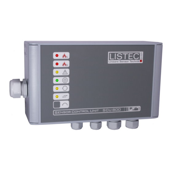
d-LIST Manual INDICATORS AND OPERATION INDICATORS ALARM A: Fire alarm on sensor cable port K1. ALARM B: Fire alarm on sensor cable port K2. FAULT: Unit or sensor cable fault. POWER: Power present and internal fuse o.k. MEASUREMENT: Temperature retrieval from sensor cable. DATA TRANSFER: Data transfer on the serial interface. -
Page 44: Test
Manual d-LIST 7.2.2 TEST During inspection: Compare a formerly configured number of sensors with the number of currently active sensors. During commissioning: Compare the number of active (recognised) sensors to the number of sensors noted on plans, while installing the sensor cable ( 4.1 Imprints). It is recommended to connect and test sensor cable branches individually, so that possible faults can be isolated. -
Page 45: Commissioning
d-LIST Manual COMMISSIONING AUTOMATIC COMMISSIONING The SCU can automatically recognise all connected sensors and register these for monitoring (= auto-configured operation: 3.3.1). No extra software or equipment is required for this configuration. Note: All settings conform to a system response behaviour according to EN 54-5, class A1. -
Page 46: Inspection And Maintenance
Manual d-LIST INSPECTION AND MAINTENANCE The inspection of a d-LIST system is a quick functional test, which can be performed by briefed personnel. Maintenance of a d-LIST system can be performed by trained personnel only. INSPECTION Form 60T028 outlines the procedure and may also be used to document the inspection. ... -
Page 47: Appendix: Part Numbers
M00402 SCU 800 housing Incl. hinges, front panel foil, plugs, lid-screws & -covers M00189 SCI 800 main board Main board for SCU 800-03 / SCU 800/16 M00192 LED-IB 800 indicator board Indicator board with LEDs for SCU 800-03 M00225 REL 800/16 relay board... -
Page 48: Appendix: Dimensions
APPENDIX: DIMENSIONS SCU 800 Case material: Aluminium Ingress protection: IP 65 Colour: Grey (RAL 7040) CBO 5-SEC AND CBO 5-ESD-T 167,5 Case material: Glas fibre reinforced Polycarbonate Ingress protection: IP 66 Colour box: Grey (similar to RAL 7035) Colour cover: Red (similar to RAL 3020) M20x1,5 74,7... -
Page 49: Appendix: Opening Seccon
APPENDIX: OPENING SECCON Opening SECcon connectors: Unlocking spring clamps: 1. Loosen gland nut. Use a 3,5 mm de-burred DIN 5264 A screwdriver to 2. Use two screwdrivers to disengage the housing's unlock wires from spring clamps. latches and separate it from the connector body. Abberdaan 162 │1046 AB │...
Need help?
Do you have a question about the SCU 800/16 and is the answer not in the manual?
Questions and answers