Table of Contents
Advertisement
Quick Links
Advertisement
Table of Contents

Related Manuals for SwiftSensors 3 Series

Summary of Contents for SwiftSensors 3 Series
- Page 1 Series 3 System Manual Rev 05112022...
-
Page 2: Table Of Contents
Table of Contents 1. Table of Contents 2. General 3. Intended Use 3.1 Operating Environment 3.1.1 Gateway 3.1.1.1 Deployment Environment 3.1.1.2 Operating Temperature and Flammability 3.1.2 Sensor 3.1.2.1 Deployment Environment 3.1.2.2 Probe Environmental Limits 3.2 Hazards / Failure Conditions 3.2.1 Gateway and Sensor 3.2.1.1 Exposure and Mechanical Damage 3.3 Warnings 3.3.1 Gateway... - Page 3 5.1 Electrical Specification 5.2 Equipment Ratings 6. Equipment Operation 6.1 Accessories / Interconnects 6.1.1 Gateway 6.1.1.1 USB3.0 Ports and Cellular Modem 6.1.1.2 Optional IP67/NEMA Enclosures 6.1.1.3 Ethernet Cable Gland Installation 6.1.2 Sensor 6.1.2.1 Thermal Buffer Bottles (Glycol, Glass Bead) 6.2 Battery Replacement 6.2.1 Sensor 6.2.1.1 Battery Specifications 6.2.1.2 Battery Replacement Procedure...
-
Page 4: General
2. General System Overview Congratulations on your purchase of a Swift Sensors Wireless Monitoring and Notification System. The introduction of wireless sensors and the industrial internet of things (IIOT) are revolutionizing measurement and monitoring applications across many different industries – including foodservices, manufacturing, laboratory and pharmaceutical, facilities management, and agriculture. - Page 5 Use of product outside of recommended environments, ratings, and specifications will result in impairment or degradation of protection mechanisms. This may ultimately result in a partial or complete failure due to mishandling. Rev 05112022...
-
Page 6: Intended Use
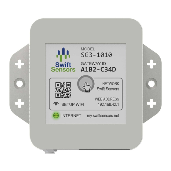
3. Intended Use 3.1 Operating Environment 3.1.1 Gateway 3.1.1.1 Deployment Environment The SG3-1010 (Shown in Figure 3.1) and SG3-1012 gateways are designed for indoor use only in a dry environment, away from water. Gateways used outdoors without proper protection may void their guarantee. While Series 3 gateways currently do not carry an IP- Rating, Swift Sensors offers IP67-rated NEMA enclosures as optional accessories for outdoor use and for use in an... -
Page 7: Hazards / Failure Conditions
3.2 Hazards / Failure Conditions 3.2.1 Gateway and Sensor 3.2.1.1 Exposure and Mechanical Damage Whenever possible, ensure that sensors and gateways are in environments away from their critical temp + humidity boundaries. Exposure to heat, humidity, and liquid outside the datasheet indicated ranges may cause a partial or total failure in gateway or sensor operation. -
Page 8: Mounting And Deployment
4. Mounting and Deployment 4.1 Operating Environment Indications 4.1.1 Gateway 4.1.1.1 Optimal Orientation For optimal wireless sensor communication, the Series 3 gateway should be mounted in the correct orientation, with the power and communication ports facing down (as shown in Figures 4.1-4.3 below). 4.1.1.2 Mounting Options Several mounting options are available for the gateway, depending on environmental factors. -
Page 9: Sensor
4.1.2 Sensor 4.1.2.1 Optimal Orientation The Series 3 sensor has optimal wireless sensor communication when mounted in the correct orientation, with an upright, readable Swift Sensors logo. See Figure 4.4 below: Figure 4.4 4.1.2.2 General Mounting Options There are multiple ways to mount Series 3 sensors, please reference Figure 4.5 below for mounting all Series 3 sensor enclosures. -
Page 10: Sensor Model-Specific Installation Guidance
Figure 4.6 Labeling Space 4.1.2.4 Sensor-Specific Installation Guidance Below is sensor-specific mounting and installation guidance that discusses unique considerations for each sensor model. As explained in Section 4.1.2.2, all sensor enclosures share the same basic mounting options, but guidance is needed for external probes and special features of unique sensor models. All sensor models below carry an IP-rating of IP66 unless otherwise specified. - Page 11 Figure 4.8: Incorrect Gasket Insertion Figure 4.9: Correct Gasket Insertion Figure 4.10: Ring Lug Dimensions Rev 05112022...
- Page 12 SS3-105 The SS3-105 Remote Temperature sensor is typically used to monitor temperature inside equipment such as a walk-in cooler, refrigerator, or freezer. The temperature measurement is made from the capsule at the end of a 1-meter (3.25’) probe. Mount the sensor enclosure on the side of the equipment or on a nearby wall with two mounting screws (optimal) and place the metal temperature sensing element at the end of the probe in the desired location.
- Page 13 lead and the provided rigid, Stainless Steel Immersion probe which contains the sensing element. These probes are available in different lengths (100 / 150 / 750 / 1000mm). Probe diameter is 3mm (<1/8”) for probe lengths < 500mm (1.6’), and is a 6mm (<1/4”) diameter for probe lengths >500mm (1.6’). Immersion probes are generally placed into the measurement medium and left alone, but mounting may be supported with zip-ties as needed.
- Page 14 SS3-109 SS3-109 is a Water Detection Rope sensor. A 3-meter (~10’) lead comes attached to the sensor enclosure, with a 3-meter orange water detection rope which connects to the 3-meter lead with a waterproof connector. The 3-meter lead allows for more placement options of the actual water detection rope. For water presence to be detected, the water detection rope must see at least 10% or 0.3 meters (1’+) of saturation.
- Page 15 location of the desired measurement, and mount the sensor in a safe environment (-40C to +60C) as advised in Section 4.1.2.2. Although the gland can withstand +125C, the sensor enclosure is limited to +60C due to the use of batteries. Stainless steel gland is shown below with dimensions for placement strategy (Figure 4.18). SS3-116 The SS3-116 High Temp has a 1-meter (3.25’) stainless steel-braided cable for holistic exposure to high- temperatures, such as BBQ pits, fire pits, and any situation where the cable may also be exposed to extreme...
- Page 16 SS3-301 The SS3-301 Door Sensor operates using a remote magnet, which trips the attached switch capsule to determine the door’s state (open/closed). The sensor enclosure is mounted on a wall near the door being monitored. Both switch and magnet capsules have adhesive for easy mounting on the door frame and door.
- Page 17 SS3-605 The SS3-605 4-20mA Current Sensor has a 1-meter (3.25’) cable connected to the sensor enclosure, terminating with red and black leads. The red lead connects to a terminal block, or any preferred method of connection to the current loop Positive (+). The black lead connects to a terminal block, or any preferred method of connection to the current loop Negative (-).
- Page 18 Figure 4.22 SS3-612 The SS3-612 0-10Vdc Sensor has a 1-meter (3.25’) cable connected to the sensor enclosure, terminating with red and black leads. The red lead connects to positive (+), and the black lead connects to negative (-) or GND. The two most typical applications for this sensor are DC Voltage Monitoring and Industrial/Transducer Monitoring.
- Page 19 Wire connections, similarly to the SS3-612, will be made directly to provided terminals on an object of measurement, or can be connected “wire-to-wire” if necessary for the application. Leads may also be soldered into place for permanent installations if needed. SS3-617-30/100/200 The SS3-617 family are Sensors with 1-meter cables (2-meters for SS3-617-200) which connect to high-quality current transformer clamps (“CTs”), which arrive pre-calibrated.
- Page 20 board receptacle (Figure 4.24). It may also be removed using a thumb and index finger, applying a pulling force. It may help to add lateral force to the pulling force to “wiggle” the connector out gently. (Figure 4.25) Note: When the external connector is removed, Hardware Alerts may be triggered on an existing measurement, due to loss of connection.
- Page 21 2. Having multiple measurements connected at once will not harm the SS3-615, although data may only be gathered for one single measurement at a time. 3. Any Measurement mode may include a Digital Out Switch Mode, configurable by the customer. 4.1.2.5.2 SS3-615 Digital Out Switch: Information on connections, indications, and typical usage of the Digital Out Switch (DOUT) is available on the previously referenced “SS3-615 Configuration Guide”...
- Page 22 a. Figures 4.27-4.33 show the effects on battery lifetime as resistance decreases while using Control Loop Times <=60s in “Automatic Mode.” Power Consumption for Resistance Measurements 10kΩ+, Table 4-1 and Figure 2.25 may be referenced. The tables below are relevant to “Resistance Mode,” and no other measurements. Figure 4.27 Figure 4.28 Figure 4.29...
- Page 23 Figure 4.33 Rev 05112022...
-
Page 24: Technical Specification
5. Technical Specification 5.1 Electrical Specification Electrical specification data for each Series 3 gateway and sensor model is located in Appendix A: Data Sheets. 5.2 Equipment Ratings Equipment ratings data for each Series 3 gateway and sensor model is located in Appendix A: Data Sheets Rev 05112022... -
Page 25: Equipment Operation
6. Equipment Operation 6.1 Accessories / Interconnects 6.1.1 Gateway Accessories 6.1.1.1 USB3.0 Ports and Cellular Modem The Series 3 gateway has two operational USB3.0 ports. These USB3.0 ports may provide 5V @ 0.9A (4.5W) total for general use. Swift Sensors offers an optional cellular modem which may be used on either of the two USB3.0 ports, with “plug-and-play”... - Page 26 Figure 6.2 Figure 6.3 Mounting: Figure 6.4 shows the included mounting brackets and screws included with the SG3-NEMA-1010 enclosure. There’s also an included information packet that gives detailed mounting instruction. Figures 6.5, 6.6 show the SG3-NEMA-1010 with mounting flanges installed. Please reference the included literature for desired mounting once flanges are installed.
- Page 27 6.1.1.2.2 NEMA Enclosure for both Gateway + Cellular Modem (SG3-1010/1012 + SG3-CNM-01) The larger size NEMA gateway enclosure can accommodate a Series 3 Gateway (SG3-1010 or 1012) and a cellular modem. Swift Sensors recommends this to be purchased with equipment already installed. Figure 6.7, 6.8 shows all the different items inside the enclosure, and Figure 6.9 shows the external components of this enclosure.
-
Page 28: Ethernet Cable Gland Installation
NOTE: Cellular Modem Mount + Antenna Mounts come pre-installed even in the assembly kit. Mounting: The Larger NEMA enclosure that can house the cellular modem accessory and a gateway comes with a hardware pack similar to the SG3-NEMA-1010 enclosure. Instead of mounting flanges, the hardware pack contains 4 brackets with 4 screws. - Page 29 Step 3: Thread the ethernet cable through the first outer-cuff, so that outer-cuff threading will be facing in the correct direction on the proper end of the ethernet cable. (Figure 6.11) Step 4: Match the Inner-cuff to be flush, inside the first outer-cuff, to prepare for the second outer-cuff.(Figure 6.12).
-
Page 30: Sensor
6.1.2 Sensor Accessories 6.1.2.1 Thermal Buffer Bottles (Polyethylene Glycol/Glass Bead) Thermal buffers are used on temperature sensors for two reasons; first is to avoid transient temperature swings and second is to have a uniform medium as a reference. This improves accuracy and keeps alerts toa minimum, without missing critical temperature swings. -
Page 31: Battery Replacement
Figure 6.18: Capsule may be grabbed with Pliers Figure 6.19 Figure 6.20 Step 3 (SS3-105): If bottle insert was placed into thermal buffer bottle, and SS3-105 probe is pushed into thermal buffer, make sure the probe capsule is centered in the bottle, and installation is complete. The bottle may be placed where desired. - Page 32 1. Replacement with L92 "Ultimate Lithium" AAA is recommended. Traditional alkaline AAA’s will function with a slightly shorter lifetime (30% less) and will result in incorrect Battery % readings in the Swift Console. 2. Remove the four mounting Screws on the bottom of the sensor. 3.
-
Page 33: Appendix A: Data Sheets
Appendix A: Data Sheets A. Gateway SG3-1010 - Gateway for Series 3 Sensors SG3-1012 - Gateway for Series 3 Sensors and Series 2 RF Sensors B. Sensor SS3-101 - Wireless Temperature, Humidity, and Dew Point Sensor SS3-102 - Wireless Water Resistant Temperature Sensor SS3-103 - Wireless Ring Lug Temperature Sensor SS3-104 - Wireless Medical Grade Temperature Sensor SS3-105 - Wireless Remote Temperature Sensor... - Page 34 SS3-617-200 – Wireless 0-200Arms Current Transformer Meter C. Accessories SG3-NEMA-1010-KIT - NEMA + IP67 Rated Enclosure for SG3-1010 Gateway Only SG3-NEMA-CNM1-KIT - NEMA + IP67 Rated Enclosure for SG3-1010/1012 Gateways and Cellular Modem SG3-CNM-1 - USB Cellular Modem Accessory for Series 3 Gateways SS-TB1-120 - 120mL Polyethylene Glycol Thermal Buffer Medium Bottle with Insert SS-TB2-200 - 200g Fine Glass Bead Thermal Buffer Medium Bottle with Insert Rev 05112022...
-
Page 35: Appendix B: Compliance Notices
Appendix B: Compliance Notices A. FCC Compliance Notice This device complies with part 15 of FCC rules. Operation is subject to the following two conditions: 1. This device may not cause harmful interference. 2. This device must accept any interference received, including interference that may cause undesired operation.
Need help?
Do you have a question about the 3 Series and is the answer not in the manual?
Questions and answers