Table of Contents
Advertisement
Quick Links
Advertisement
Table of Contents

Related Manuals for AFM STC-WSN300-2M

Summary of Contents for AFM STC-WSN300-2M
- Page 1 WSN GEN-S Steam Heat Shrink Tunnel User Guide...
- Page 2 Abbreviations 4510012 - REV F – 220621...
- Page 3 Abbreviations WSN GEN-S Models: STC-WSN300-2M STC-WSN600-2M User Guide Revised 6/21/22 P/N 4510012 – Rev F Copyright and Trademarks Copyright ©2022 American Film and Manufacturing. All rights reserved. All trademarks and brand names are the property of their respective owners. 7041 Boone Avenue North...
-
Page 4: Table Of Contents
Conveyor ..........................20 Stand ..........................21 Boiler Assembly ........................22 Electrical System .........................25 System Specifications ....................26 System Dimensions ....................27 STC-WSN300-2M GEN-S ....................27 STC-WSN600-2M GEN-S ....................28 Installation and Setup ................29 General Setup Considerations ..................29 Material Handling ........................29 Work Area ...........................30 Maintenance Access ......................30... - Page 5 Abbreviations Humidity ..........................30 Water Access ........................30 Codes and Regulations .......................30 Traffic Patterns ........................31 Unpacking ........................32 Physical Setup ......................32 Plumbing and Valve Connections ................33 Power Connection ....................... 36 Operation ....................37 Performing Initial Startup/Startup After 1 Week Idle ............ 37 Adjusting the Steam Manifolds ..................
- Page 6 Abbreviations Exploded Diagrams ..................... 72 Stand ..........................72 Tunnel ..........................74 STC-WSN300-2M GEN-S ....................76 STC-WSN600-2M GEN-S ....................77 Boiler ...........................78 Warranty Statements ................81 Limitations ........................81 Repairs ........................81 Shrinking Quality ......................81 Shipping Policy......................81 Exclusions ........................81 Warranty Verification ....................81 Warranty Eligibility .......................
-
Page 7: Abbreviations
Abbreviations Abbreviations The following abbreviations are used throughout this User Guide: Abbreviation Meaning Abbreviation Meaning Alternating Current PETG Polyethylene Terephthalate Glycol Amperes A plastic material used for label film Celsius Personal Protective Equipment Centimeters Pounds per square inch Fahrenheit PSIG Pounds per square inch gauge Hertz Polyvinyl Chloride... - Page 8 Abbreviations 4510012 - REV F – 220621...
-
Page 9: Safety
Safety Safety When installing, operating, and maintaining the STC-WSN GEN-S Steam Heat Shrink Tunnel, follow these safety practices. Warnings • Study this User Guide thoroughly before operating the GEN-S. Failure to do so may result in serious injury, damage to the machine, and/or may void the warranty. When unpacking and setting up the GEN-S, use proper lifting and safety practices. - Page 10 Service and maintenance beyond what is described in this User Guide should be • performed by a trained and qualified technician. If in doubt, contact AFM or your authorized distributor. All operators must strictly observe these guidelines and ensure that the GEN-S is •...
-
Page 11: Understanding Safety Notifications
Safety Understanding Safety Notifications DANGER: Indicates a hazardous situation which, if not avoided, will result in death or serious injury. WARNING: Indicates a hazardous situation which, if not avoided, could result in death or serious injury. CAUTION: Indicates a hazardous situation which, if not avoided, could result in minor or moderate injury. -
Page 12: Cautions
Safety Cautions When installing, operating, and maintaining the STC-WSN GEN-S Steam Heat Shrink Tunnel, observe these cautions. Wear Safety Equipment: Wear necessary Personal Protective Equipment (PPE), including safety glasses/goggles and heat-resistant work gloves. Electrical Hazard: Do not open cover. No user-serviceable parts inside. Electrical Ground Hazard: Ensure that unit is properly grounded. -
Page 13: Equipment
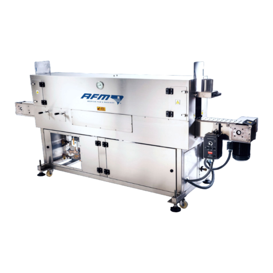
Equipment Equipment Included Equipment Steam Tunnel • Conveyor • Stainless Steel Stand with Leveling Feet • • Integrated Boiler Electrical System and Controls • STC-WSN GEN-S Steam Heat Shrink Tunnel (Front View) Steam Tunnel Stand Conveyor with Feet Boiler System Electrical Conveyor Enclosure... -
Page 14: Optional Equipment
GEN-S setup: Sleever A Sleever applies labels to products before the GEN-S shrinks those labels onto the products. A Sleever is not included with the GEN-S, but AFM offers several models depending on label size and production speed. AFM LX-150... -
Page 15: Conveyor
Equipment Conveyor A Conveyor is needed to carry products to and from the built-in Conveyors of the GEN-S. AFM can offer Conveyor solutions as required. 4510012 - REV F – 220621... -
Page 16: Accumulation Table
An Accumulation Table is not included with the GEN-S, but can be used to stop, hold, and release products after the GEN-S has fixed the labels onto them. Two height-adjustable Accumulation Table options are available from AFM’s sister company, Eastey – the 36” diameter TT36 and the 48” diameter TT48. -
Page 17: Introduction
Manifold adjustments and controls are done from both sides of the Tunnel. Features of the GEN-S Steam Heat Shrink Tunnel from AFM include: Fully integrated 30 kW boiler to generate its own steam where in-plant steam is not •... -
Page 18: System Components
Introduction System Components The STC-WSN GEN-S Steam Heat Shrink Tunnel is composed of five general components – the Steam Tunnel, Conveyor, Stand, Boiler Assembly, and Electrical System. STC-WSN GEN-S Steam Heat Shrink Tunnel Steam Tunnel Conveyor Stand System Electrical Enclosure Boiler 4510012 - REV F –... -
Page 19: Steam Tunnel
Introduction Steam Tunnel The Steam Tunnel sends pressurized steam heat through two tiers of pipes, called Manifolds, that extend down the length of the Tunnel. The Manifolds have small holes at regular intervals along their length, and the steam is forced out of the holes and directed at products as they pass through on the Conveyor. -
Page 20: Conveyor
Introduction Conveyor The Conveyor carries products into, through and out of the Steam Tunnel. Parts of the Conveyor are labeled below. Conveyor Conveyor Output End Input End Controller Conveyor Speed Conveyor Motor Conveyor Start/Stop System Main Power Switch 4510012 - REV F – 220621... -
Page 21: Stand
Introduction Stand The Stand contains or supports the Boiler, Electrical System, and all of the other components of the system. Parts of the Stand are labeled below. Stand Lower Manifold Steam Upper Manifold Steam Pressure Controls Pressure Controls Water Inlet Boiler Electrical Water... -
Page 22: Boiler Assembly
Introduction Boiler Assembly The Boiler Assembly is located inside the Boiler Enclosure on the left (looking from the front) below the Conveyor. It boils water to provide heated steam to the Steam Tunnel. Parts of the Boiler Assembly are labeled below. WARNING: Electrical Hazard. - Page 23 5A Fuse Controller Steam Feed Motor Solenoid Holder Power Switch Valve Strainer (Inside) Upper Sight Glass Valve Sight Glass Lower Sight Glass Valve AFM-4510012-00025-01 Drip Pressure High Limit Blowdown Electrical Valve Gauge Pressure Valve Cabinet Control Boiler Manual Operating Blowdown Control...
- Page 24 Introduction Boiler Assembly (Back) Water Solenoid Probes (3) Water Feed Motor Emergency Relief Valve Pump Electrical Cabinet 4510012 - REV F – 220621...
-
Page 25: Electrical System
Introduction Electrical System The Electrical System is located inside the Electrical System Enclosure on the right (looking from the front) below the Conveyor. It is mainly composed of the AC Power Box, which sends electrical power to the entire system, powering components including the Conveyor, Boiler, and system Controls. -
Page 26: System Specifications
AC 3-Phase, 240/480 V, 50/60 Hz Machine Construction Stainless steel frame and construction Motors 230 VAC, 3-Phase,1/2 Horsepower Zones and Tiers 1 zone with 2 tiers Length: 118.1″ 300.0 cm STC-WSN300-2M Width 31.5″ 80.0 cm GEN-S Height: 49.0″ 124.5 cm Machine Dimensions Length: 236.2”... -
Page 27: System Dimensions
Introduction System Dimensions STC-WSN300-2M GEN-S Front View Top View Exit View Entry View 4510012 - REV F – 220621... -
Page 28: Stc-Wsn600-2M Gen-S
Introduction STC-WSN600-2M GEN-S Front View Top View Exit View Entry View 4510012 - REV F – 220621... -
Page 29: Installation And Setup
Installation and Setup Installation and Setup General Setup Considerations In addition to providing proper space for the STC-WSN-GEN-S Steam Heat Shrink Tunnel, and ensuring that it will be in the desired section within the assembly line chain, consider other factors, including: Material Handling The most critical factor for consistently achieving superior quality heat shrinking is product handling. -
Page 30: Work Area
All plumbing connections should be made by a licensed plumber who works in accordance with all applicable national and local plumbing codes. They should inform themselves of local and state Boiler Certification regulations before proceeding with installation. AFM is not responsible for installation in ways that violate code or other regulations. -
Page 31: Traffic Patterns
Installation and Setup Traffic Patterns Careless positioning can result in damage to the GEN-S. An example is locating the machine where it can be accidentally knocked by a Forklift, or similar placement in an area of predictable traffic. Keep the system away from known traffic paths. ATTENTION: Locate the GEN-S away from known traffic paths. -
Page 32: Unpacking
Installation and Setup Unpacking When unpacking the GEN-S, be careful not to scratch or otherwise damage the system. Check for Shipping Damage: Examine the unit for obvious damage • Check connections, and tighten if needed • Physical Setup The GEN-S is easy to set up and incorporate into a production line. Needed for Physical Setup: Forklift to remove the unit from the crate •... -
Page 33: Plumbing And Valve Connections
Installation and Setup Plumbing and Valve Connections The GEN-S requires a connection to a consistent source of filtered or softened water. ATTENTION: Only clean filtered or softened water should be used. Failure to do so will result in shortened Boiler life and cause an increase in sediment buildup, which will negatively impact performance. - Page 34 Tank (Part Number 4503267; customer-provided – should be translucent so that water level and color is visible) or a proper discharging location. WARNING: Do not reduce the Blowdown Outlet from its original size or connect a smaller diameter Blowdown Hose. Connecting to the Blowdown Outlet AFM-4510012-00025-01 Blowdown Outlet Blowdown Outlet...
- Page 35 Hose to a suitable drain. NOTE: Check local regulations and codes. Connecting to the Water Outlet Water Outlet Water Outlet AFM-4510012-00040-01 Check system for leaks. If found, call AFM Technical Support. 4510012 - REV F – 220621...
-
Page 36: Power Connection
Have a Licensed Electrician connect a Power Cord that has a a 3-Phase, 480 VAC 50/60 Hz grounded plug (not included) to the Main Disconnect On/Off Switch Box. 3-Phase Plug Connection AFM-4510012-00034-01 Ensure that the Tunnel Main Power Switch is in the Off position before connecting to AC power. -
Page 37: Operation
Verify that the two Sight Glass Valves are open (turned counterclockwise). Verify that the Drip Valve at the bottom of the sight glass is closed (turned clockwise). Boiler Controller Power Switch (Off) Upper Sight Glass Valve Lower Drip Sight Valve Glass Valve AFM-4510012-00036-01 AFM-4510012-00025-01 4510012 - REV F – 220621... - Page 38 Operation Verify that the Boiler Controller Power Switch is off. Close the Steam Valve (perpendicular to the line). Close the Blowdown Valve (perpendicular to the line). AFM-4510012-00037-01 AFM-4510012-00038-01 Steam Valve Blowdown Valve (Closed) (Closed) Confirm that the Water Inlet is connected to a filtered or softened water source.
- Page 39 Operation Turn on the water supply. Confirm the facility main electrical power to the GEN-S is on. Turn the System Main Power Switch on. AFM-4510012-00041-01 AFM-4510012-00042-01 System Main Boiler Controller Power Switch Power Switch (On) (On) Turn the Boiler Control Power Switch on.
- Page 40 Operation Turn the Boiler Control Power Switch off. AFM-4510012-00036-01 AFM-4510012-00044-01 Boiler Controller Blowdown Power Switch Valve (Off) (Open) Slowly open the Blowdown Valve (parallel to the line) until the water drains from the Boiler. WARNING: The water will be hot. Use caution to avoid burns.
- Page 41 Operation AFM-4510012-00040-01 AFM-4510012-00039-01 Manifold Zone Output Valves Conveyor Controller Access Door (Open) Power Switch Open the Zone Output Valves. The GEN-S is now ready to run product. IMPORTANT: Once initial startup has been completed, perform the blowdown procedure every 4 hours during the first week of operation (see “Blowdown Procedure”...
-
Page 42: Adjusting The Steam Manifolds
At each end of the Tunnel, use a 13mm Wrench to loosen the Cap Screws that hold the Manifold Height Adjusts in position. Manifold Manifold Height Height Adjusts Adjusts Screws (Up/Down) (Up/Down) AFM-4510012-00072-01 AFM-4510012-00072-01 4510012 - REV F – 220621... - Page 43 Operation Adjust the height of the Upper and/or Lower Manifolds as desired. The Manifolds do not need to remain parallel to one another. Maximum height variation for a single Manifold is 7.5” (19.1 cm). Adjusting Steam Manifold Height (Front View) Upper Manifold Height Adjust (Up/Down)
-
Page 44: Adjusting Manifold Depth
Inside one of the Manifold Access Doors, use a 10mm Wrench to loosen the Cap Screws holding the Upper and Lower Manifold Depth Adjusts in position. Screws Manifold Depth Adjusts (In/Out) Screws AFM-4510012-00072-01 AFM-4510012-00072-01 Adjusting Steam Manifold Depth (Top View) Screws Steam Conveyor Manifolds... - Page 45 Operation Adjust the depth of the Upper and/or Lower Manifolds as desired. The Manifolds do not need to remain parallel to one another. Maximum depth variation for a single Manifold is 3.75” (9.5 cm). When satisfied with the depth positions of the Manifolds, use the 10mm Wrench to retighten the Cap Screws to lock the Manifold Depth Adjusts in place.
-
Page 46: Adjusting Manifold Angle
To redirect the angle of the Steam Jets on a Manifold, use a 13 mm Wrench to loosen the Cap Screws on the Manifold Cuffs on both ends of the desired Manifold (just inside each opening of the Steam Tunnel). AFM-4510012-00050-01 AFM-4510012-00068-01 Manifold... -
Page 47: Running Product
To run product through the GEN-S Steam Heat Shrink Tunnel, follow the procedure below. Total Time Required Before Running Product: At least 20 minutes • To Run Product: Turn the System Main Power Switch on. AFM-4510012-00041-01 AFM-4510012-00038-01 Blowdown Valve System Main Power Switch (Closed) (On) Ensure that the Blowdown Valve is closed. - Page 48 10 minutes until the Boiler Pressure Gauge stabilizes at 40–80 PSIG. IMPORTANT: The High Limit Control and Operating Pressure Controls are preset at the factory and do not need to be adjusted. Turn on the Conveyor by clicking the Conveyor Power Switch up. AFM-4510012-00025-01 AFM-4510012-00040-01 Conveyor Controller Sight Glass...
- Page 49 Operation NOTE: If the pressure exceeds 85 PSIG, a Pressure Tab on the top of the High Limit Pressure Control pops out and needs to be reset by pushing it down. Run some test product through the Steam Tunnel and adjust Conveyor speed and Manifolds as needed.
-
Page 50: Shutting Down
To Shut Down the GEN-S: Turn the Boiler Controller Power Switch off. Allow the Conveyor to move any remaining product out of the Tunnel. Turn the Conveyor Power Switch off Turn the System Main Power Switch off. AFM-4510012-00036-01 AFM-4510012-00040-01 AFM-4510012-00053-01 Boiler Controller System Main... -
Page 51: Maintenance
ATTENTION: Do not attempt to perform maintenance or repairs other than those described in this User Guide. Failure to follow this directive can result in injury, damage the equipment, and will void the warranty. If in doubt, contact your AFM distributor. -
Page 52: Maintenance Schedule
Maintenance Maintenance Schedule Adherence to the maintenance schedule below will extend the life of the GEN-S, ensure the best performance, and reduce the likelihood of injury. Frequency Maintenance Task Visually check the water level in the Sight Glass. Every hour during operation Check for leaks from the Sight Glass. -
Page 53: Blowdown Procedure
To Perform Blowdown Procedure: Turn the Boiler Controller Power Switch off. Allow the Conveyor to move any remaining product out of the Tunnel. Turn the Conveyor Power Switch off Turn the System Main Power Switch off. AFM-4510012-00036-01 AFM-4510012-00040-01 AFM-4510012-00053-01 Boiler Controller System Main... - Page 54 Allow the Boiler pressure to decrease to 10 PSIG according to the Pressure Gauge. Pressure Gauge AFM-4510012-00025-01 Attach the Blowdown Hose (connected to a drain or a Blowdown Tank) to the Blowdown Outlet). WARNING: The Blowdown Outlet may be hot. Use caution to avoid burns.
- Page 55 Open the Blowdown Valve slowly by turning the handle until valve is fully opened (parallel to the line) for approximately 3 seconds, and then turn the handle back to the closed position (perpendicular to the line). AFM-4510012-00044-01 AFM-4510012-00038-01 Blowdown Valve...
-
Page 56: External Cleaning
Maintenance External Cleaning The exterior of the GEN S may require occasional cleaning due to environmental contaminants. To clean the external components, gently wipe them with a clean cloth and cleaning spray. Manual Cleanout Every 3 months, a manual cleanout of the Boiler Tank and Heating Elements is necessary. ATTENTION: Do not use boiler cleaning compounds. - Page 57 Maintenance Remove the Electrical Cabinet Front Panel to access the inside of the Electrical Cabinet. Electrical Cabinet Electrical Cabinet Front Panel Carefully disconnect the Conductor Wires from the Conductors, noting which Wire is connected to which Conductor. IMPORTANT: Make note of the original wiring arrangement of the Conductors. This information will be necessary during reassembly.
- Page 58 Maintenance Carefully pull the Heating Element away from the Boiler Tank, preserving the orientation of the Heating Element. The inside of the Boiler Tank should now be accessible. Use water and a Long-Handled, Soft Wire Brush to scrape away any scale or sediment buildup from inside the tank.
- Page 59 Boiler Controls and other components. If needed, see the Boiler Owner’s Guide (included) for additional location of parts. Reinstall the Electrical Cabinet Front Panel. Inside of a Boiler that has not been Cleaned Out for a Year AFM-4510012-00076-01 4510012 - REV F – 220621...
-
Page 60: Cleaning Or Replacing The Strainer
Strainer in water, and gently clean it inside and outside with a toothbrush. If the Strainer cannot be adequately cleaned, it may need to be replaced. Strainers (Part Number 4502783) are available from AFM. Place the new or cleaned Strainer back into the Y of the Pipe, oriented as it was before, and use the Adjustable Crescent Wrench to close the Pipe Plug again. -
Page 61: Checking And Cleaning The Probes
Maintenance Checking and Cleaning the Probes Every 3 months, check and clean the Probes that check the water level inside the Boiler. NOTE: Only two of the three Probes are used. The third Probe is included as a spare, which can be cut to match the length of the Probe that it is replacing. - Page 62 Maintenance Inspect the Probes for any scale buildup. Use a Scotch Brite pad to carefully and gently remove scale from each Probe. ATTENTION: Do not use hard objects or sharp force to break up the scale, as this can damage the Probes and potentially void the warranty. Remove all the old Plumber’s Tape from the threads of the Probes.
-
Page 63: Troubleshooting
Troubleshooting Below are some common problems that may be encountered during steam heat shrinking. If other issues occur that are not covered in this section, call your authorized AFM distributor for assistance. WARNING: Live steam and burn hazard. Use caution. Failure to follow this directive can result in serious injury. - Page 64 (Part Number 4500812). Fuses are inside the AC Power Box (see “Electrical System” on page 25). Contact AFM for guidance on changing the Fuses. Fuses are blown. (Lack of steam Check the three Fuses and pressure may be accompanied replace any or all of them as by a “bang”).
- Page 65 Pressure Controller on the Boiler Replace the Pressure Controller has failed. (Part Number 4503284). Contact AFM for guidance. There is Boiler pressure, but Leaky or blocked Hose. Contact AFM for guidance. no Steam coming out of Manifolds. 4510012 - REV F – 220621...
- Page 66 Troubleshooting 4510012 - REV F – 220621...
-
Page 67: Electrical Schematics
Electrical Schematics Electrical Schematics Complete System: WSN GEN-S 4510012 - REV F – 220621... -
Page 68: Boiler
Electrical Schematics Boiler 4510012 - REV F – 220621... -
Page 69: Parts List
Parts List Parts List Recommended Spare Parts List Tunnel Part Number Description Quantity 4500773 FUSE UL CLASS CC MID. KLDR-10 600V 4500777 FUSE UL CLASS CC MID. ATD-R 5A 600V 4500812 FUSE-50A LPJ-SP Boiler Part Number Description Quantity 4502944 CONTROL BOARD-MAB BOILER 240V 4503256 SIGHT GLASS, MAB30 BOILER 6.5"... -
Page 70: Additional Parts
Parts List Additional Parts Part Number Description Quantity 055029-018 WASHER-FLAT 1/4 SST 058502-854 WIRE-UL 1007,16AWG,GRN/YEL 058503-500 WIRE-UL 1015,16AWG,BLK 058503-502 WIRE-UL 1015,16AWG,RED 058503-509 WIRE-UL 1015,16AWG,WHT 058503-900 WIRE-UL 1028, 8AWG,BLK 36.5 058503-905 WIRE-UL 1015,8AWG,GRN 062733-003 LUG-RING,16-14G,8 STUD 062737-001 LUG-SPADE,16-14G,5-6 STUD 062740-001 LUG-FISO,16-14G,.032X.250 080837-002 TERM BLOCK-GND,108A,USLKG 16N 091183-001... - Page 71 Parts List Part Number Description Quantity 4502719 FITTING, 37* FLARED 1/2" 4502722 HOSE, BRAIDED S.S. 3/4" X 24" 4502723 FITTING, 37* 3/4"NPT BRASS 4502725 HOSE, BRAIDED S.S. 1/4" X 30" 4502726 ENCLOSURE, FIBERGLASS 15X13X7 4502727 BOILER, ELECTRIC 30KW 100PSI 4502733 PANEL, FOR FIBERGLASS ENCLOSURE 4502734 SWITCH, DISCONNECT 40HP NEMA 4X...
-
Page 72: Exploded Diagrams
Parts List Exploded Diagrams Stand Drawing Number: YS130EX2-01 4510012 - REV F – 220621... - Page 73 Parts List Item Part Number Description Specification Quantity 4505240 Caster 3” x 1” 4503330 Base M20X150L add Nut 4500892 Door Hinge 14104 4505221 Galvanized Nut N-30M6 4505242 Round Lock C-408A Item Part Number Description Specification Quantity 4505255 Body AFMYS130EX1-OP01 4505254 Repair Board AFMYS130EX1-OP01 4505253...
-
Page 74: Tunnel
Parts List Tunnel Drawing Number: YS130EX2-02 4510012 - REV F – 220621... - Page 75 Parts List Item Part Number Description Specification Quantity 4500892 Door Hinge 14104 4502388 Steam Valve Handle CB50M6 4505220 Thermometer 3”X0.5X1/2”X50MMX200C/F 4505221 Galvanized Nut N-30M6 4500249 Bow Handle AHG110 4505223 Door Latch C 12-A (#66) 4505204 Ball Valve SVF1316-020 1/4”PT 4505224 Pipe Fittings SUTS-002 Outer Teeth Tee1/4”H 4505225...
-
Page 76: Stc-Wsn300-2M Gen-S
Parts List STC-WSN300-2M GEN-S Drawing Number: YS130EX2-03 Item Part Number Description Specification Quantity 4502950 Conveyor W150XL3000 3 Ø 380V/60HZ Item Part Number Description Specification Quantity 4505255 Body AFMYS130EX1-OP01 4505239 Hood AFMYS130EX1-OP02 4505229 Hose Support Plate AFMYS130EX1-OP24 4505256 Drip Tray AFMYS130EX1-OP04... -
Page 77: Stc-Wsn600-2M Gen-S
Parts List STC-WSN600-2M GEN-S Drawing Number: YS130EX2-03 Item Part Number Description Specification Quantity 4505257 Conveyor W150XL6000 3 Ø 380V/60HZ Item Part Number Description Specification Quantity 4505255 Body AFMYS130EX1-OP01 4505239 Hood AFMYS130EX1-OP02 4505229 Hose Support Plate AFMYS130EX1-OP24 4505256 Drip Tray AFMYS130EX1-OP04 4505258 Drip Tray AFMYS130EX1-OP29... -
Page 78: Boiler
Parts List Boiler 4510012 - REV F – 220621... - Page 79 Parts List Inside Boiler Electrical Cabinet 4510012 - REV F – 220621...
- Page 80 Parts List Item Part Number Description Specification Quantity 4502796 Solenoid Valve Ware ½” 120V EVW3120 4503692 Ball Valve ½”, 600WOG 150WSP VALBAC3 4503274 Pump Motor 1/4HP 115V MTR1 4502781 Rotary Vane Pump MTP200 4503494 Safety Valve ¼” x ¾” 100psi VALSA34100 4502780 Probe...
-
Page 81: Warranty Statements
Warranty Statements Warranty Statements American Film & Machinery (AFM) warrants that all the products it ships will be in good working order and free from defects in material and workmanship for a period of one year from the date of shipment by AFM and will conform to the published specifications for that product. -
Page 82: Warranty Eligibility
Customer is required to return the defective component to AFM. If, after 30 days, AFM has not received the defective component, the customer will be invoiced for the replacement component. -
Page 83: Technical Support
AFM reseller or AFM Technical Support. Phone: 714-974-9006 Fax: 763-795-8867 Email: info@afmsleeves.com Web: www.afmsleeves.com Thanks again for your purchase of AFM products. We are pleased to be a part of your shrink sleeving needs. 4510012 - REV F – 220621... - Page 84 Technical Support 4510012 - REV F – 220621...
Need help?
Do you have a question about the STC-WSN300-2M and is the answer not in the manual?
Questions and answers