
Subscribe to Our Youtube Channel
Related Manuals for Fly Products RIDER Series


Summary of Contents for Fly Products RIDER Series
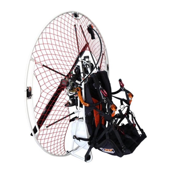
- Page 1 ASSEMBLY MANUAL RIDER SERIES VERSION 2 – 04/2014 Products © s.r.l. Copyright by Via Perù n. 30 63013 GROTTAMMARE (AP) - ITALY tel./fax +39.735.632486 www.flyproducts.com fly@flyproducts.com...
- Page 2 ASSEMBLY MANUAL REL . 1.1 INDEX FRAME ASSEMBLY HARNESS SIZE ADJUSTMENT FITTING THE HARNESS HIGH ATTACK FITTING THE HARNESS DEDICATED TO LOW ACTIVE ATTACK (A.S.C.) OPTIONAL FITTING THE EMERGENCY INTO ASC HARNESS OPTIONAL PROP MOUNTING MULTIFUNCTION HANDGRIP WARRANTY ___________________________________________________________________________ PRODUCTS ©...
-
Page 3: Frame Assembly
ASSEMBLY MANUAL REL . 1.1 FRAME ASSEMBLY Photo frame Assembly common to paramotors: Thrust, Race c, Kompress, Sprint, Jet. • Step 1: assembling the outer frame Starter manual section Supports Support Assembly (only manual starter) Step 2: Assembling the top section of the external frame Assemble the two semicircles Continue side grafting over Assemble the cage from top... - Page 4 ASSEMBLY MANUAL REL . 1.1 Punto 3 : Bloccaggio dei velcri Hook network cord on both Upper Velcro sides Tighten the bottom with velcro tape on both sides Tighten the upper with velcro tape on both sides DOUBLE CIRCLE VERSION ___________________________________________________________________________ PRODUCTS ©...
- Page 5 ASSEMBLY MANUAL REL . 1.1 STANDARD HARNESS SIZE ADJUSTMENT (DOUBLE SYSTEM: HIGH AND LOW) Find the most suited to your needs and verify in the Simulator Cut along the dotted line to get size M. Adjusting harness zip size M. Zip harness adjustment size L.
- Page 6 ASSEMBLY MANUAL REL . 1.1 FITTING THE HIGH ATTACK HARNESS The harness is attached to the frame on three anchor points: - top with two butterfly bolts, - to the side with two spacers, - at the bottom with two adjustable straps. 1) Upper hooks harness with two Butterfly bolts Attach the harness to the chassis with the plate...
- Page 7 ASSEMBLY MANUAL REL . 1.1 Assembly of the distance bars Insert the distance bar into the square slot located on the Central frame and close the Velcro straps. Lateral belt attachment Fasten the webbing at maximum length 4) Fastening shoulder webbing Attach the webbing to the right and left of the frame ___________________________________________________________________________...
- Page 8 ASSEMBLY MANUAL REL . 1.1 FITTING THE HARNESS DEDICATED TO LOW ACTIVE ATTACK (A.S.C.) OPTIONAL The harness is fastened to the frame on three anchor points: at the top with two Butterfly bolts sideways with two distance bar and bottom with three belts. 1) Upper hooks harness with two Butterfly bolts Attach the harness to the chassis with the plate and...
- Page 9 ASSEMBLY MANUAL REL . 1.1 ASC BAR SETTINGS FOR PARAMOTORS WITH GEARBOX REDUCTION ACCORDING TO THE PILOT WEIGHT A = FOR PILOTS OVER TO 75 KG. (165 LB.) B = FOR PILOTS UP TO 75 KG. (165 LB.) ___________________________________________________________________________ PRODUCTS ©...
- Page 10 ASSEMBLY MANUAL REL . 1.1 ASC BAR SETTINGS FOR PARAMOTORS WITH BELT DRIVE REDUCTION ACCORDING TO THE PILOT WEIGHT A = FOR PILOTS OVER TO 75 KG. (165 LB.) B = FOR PILOTS UP TO 75 KG. (165 LB.) ___________________________________________________________________________ PRODUCTS ©...
- Page 11 ASSEMBLY MANUAL REL . 1.1 HANGING STRAP AND BACK-UP STRAP CONFIGURATION BACK-UP PAY CLOSE ATTENTION TO THE STRAPS POSITION ___________________________________________________________________________ PRODUCTS © Copyright by s.r.l. Pag. 11...
- Page 12 ASSEMBLY MANUAL REL . 1.1 S = shoulder extension webbing configuration D = ASC strap setting to limit the bars travel upward ( the "A" angle should be between 85 e 90 degrees ) B = loosly attach the harness to the frame allowing the harness to slide up and down RIGHT WRONG Adjust this strap to raise the harness seat plate to a parallel position between your body and the...
- Page 13 ASSEMBLY MANUAL REL . 1.1 VERIFY ALL YOUR SETTINGS ON A SIMULATOR PRIOR TO YOUR FIRST FLIGHT The paramotor thrust line angle with the engine OFF should be between 15 to 25 degrees ___________________________________________________________________________ PRODUCTS © Copyright by s.r.l. Pag. 13...
- Page 14 ASSEMBLY MANUAL REL . 1.1 The paramotor thrust line angle while flying should be between 0 to 5 degrees The harness back support length can be changed according to the pilot height using the zippers at the bottom to make it longer or shorter ___________________________________________________________________________ PRODUCTS ©...
- Page 15 ASSEMBLY MANUAL REL . 1.1 another way to adjust the back length is by changing the attachment plat position ___________________________________________________________________________ PRODUCTS © Copyright by s.r.l. Pag. 15...
- Page 16 ASSEMBLY MANUAL REL . 1.1 Using the belly strap This strap should be closed in flight to allow the ASC bars to work in parallel For big pilots , it is suggested to leave this strap open during take off and landing. ONCE AIRBORNE REMEMBER TO CLOSE IT AGAIN! ___________________________________________________________________________ PRODUCTS...
- Page 17 ASSEMBLY MANUAL REL . 1.1 Exit from the harness RIGHT POSITION TO LAND Extend your legs and push your chest forward. The harness seat plate will slide into position behind your body and the paramotor frame WRONG POSITION TO LAND ___________________________________________________________________________ PRODUCTS ©...
- Page 18 ASSEMBLY MANUAL REL . 1.1 FITTING THE EMERGENCY INTO ASC HARNESS OPTIONAL Side emergency Front emergency ___________________________________________________________________________ PRODUCTS © Copyright by s.r.l. Pag. 18...
- Page 19 ASSEMBLY MANUAL REL . 1.1 External constraint to cable spacer Emergency docking points ___________________________________________________________________________ PRODUCTS © Copyright by s.r.l. Pag. 19...
- Page 20 ASSEMBLY MANUAL REL . 1.1 PROP MOUNTING Mount the propeller on the motor with belt reduction: Rider Thrust The red arrow in the illustration indicates the direction of rotation of the propeller. Propeller on engine mounting with mechanical reduction: Rider Sprint, Rider Race C, Rider Jet. The red arrow in the illustration indicates the direction of rotation of the propeller.
-
Page 21: Warranty
FLY PRODUCTS provides a guarantee on materials and workmanship defects for a period of twelve (12) months from the date of purchase. The warranty applies only to the normal use of the product. The dealer from which you purchased the product, or FLY PRODUCTS, will repair the product at no additional charge. - Page 22 ASSEMBLY MANUAL REL . 1.1 VERSION 2 – 04/2014 Products © s.r.l. Copyright by Via Perù n. 30 63013 GROTTAMMARE (AP) - ITALY tel./fax +39.735.632486 www.flyproducts.com fly@flyproducts.com ___________________________________________________________________________ PRODUCTS © Copyright by s.r.l. Pag. 22...
Need help?
Do you have a question about the RIDER Series and is the answer not in the manual?
Questions and answers