Table of Contents
Advertisement
Available languages
Available languages
Quick Links
Advertisement
Chapters
Table of Contents

Related Manuals for TENTECH MD-5075x


Summary of Contents for TENTECH MD-5075x
- Page 1 5075x Digital insulation tester P. 03 User guide TENTECH CORPORATION 7330 NW 66th ST - Miami, FL 33166 Megóhmetro digital P. 37 Manual de uso Phone: +1 305 938 0389 / Fax: +1 786 401 7165 www.tentech.com...
- Page 2 MD-5075x 5 kV Insulation tester User guide GF-2015RA © 2016 TENTECH. All rights reserved.
- Page 3 Safety warnings • Before to use this instrument the User guide and Safety warnings must be read and understood. • Safety procedures and rules for working near high voltage energized systems must be observed during the use of this equipment. The generated voltages may be dangerous.
-
Page 4: Table Of Contents
2. Panel control functions ..................7 2.1. Keyboard ....................8 2.2. Display ..................... 10 3. Charging battery ....................11 4. Connecting the MD-5075x ................11 5. Use of “Guard” (G) terminal................14 6. Setting tests ..................... 15 6.1. Test voltage definition ................15 6.2. -
Page 5: Description
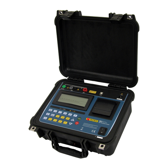
1. Description The digital insulation tester model MD-5075x is at the cutting edge of TENTECH’ insulation analyzer equipment and it is one of the more complete and sophisticated of the international market. It uses an efficient well experienced technology, which provides safe, reliable and accurate measurements of insulation resistances up to 5 TΩ, with 4 pre-selected... -
Page 6: Panel Control Functions
2. Panel control functions Voltage output terminal (-V) Zero reference terminal (+R) Guard (G) Terminal Display Keyboard High Voltage led On / Off key USB communication port Power supply input Printer... -
Page 7: Keyboard
2.1. Keyboard Function Turns the printer on/off Indicates that the printer is turned on. Hold - Freeze the last reading on the display The Hold function is on Battery - exhibits the battery charge status Indicates that the battery on the display charger is on Filter - Activates the filter that minimizes the Indicates that the filter is... - Page 8 Activated, enables programming of 25 V 25 V steps activated step tests voltages Activated, enables programming of 100 V 100 V steps activated step tests voltages Activated, enables programming of 500 V 500 V steps activated step tests voltages Selection of 500 V test voltage Indicates 500 V selected Selection of 1 kV test voltage Indicates 1 kV selected...
-
Page 9: Display
2.2. Display Measurement results in the corresponding measuring unit, elapsed time since the measurement started, selected test voltage, analogue indication by means of a bargraph and several messages to the operator are displayed on alphanumeric LCD. -
Page 10: Charging Battery
At the end of battery useful life, the battery must be recycled or disposed of properly, in order to protect the environment. Charging procedure: • Check if the MD-5075x is turned-off and connect it to the mains (AC adapter). • The charging indicator ( ) will turn on red and will remain that way until the battery is totally charged. -
Page 11: Connecting The Md-5075X
Powered-Off. Please, do check if there is no difference of potential voltages between the points where the MD-5075x shall be connected to. Please, check the same between those points and the ground. At the time of the connection and power-on, the equipment automatically enters in the voltmeter mode and begins to exhibit the circuit voltage in the display. - Page 12 Connect the red cable security terminal to the equipment (-V) output terminal, the BNC terminal of the black cable to the zero reference (+R) terminal and the “alligator” terminals to the element to be measured as indicated in the next figure. The test leads in the picture are merely illustrative.
-
Page 13: Use Of "Guard" (G) Terminal
5. Use of “Guard” (G) terminal Depending on the measurement to be made, the Guard (G) may be used or not. During the measurements, the equipment should be electrically grounded to avoid unsteady readings. When insulation is measured regarding grounding, the R terminal is connected to earth and the condition by means of which the equipment potential setting is fulfilled. -
Page 14: Setting Tests
6. Setting tests The insulation tester MD-5075x is an extremely versatile instrument that enables automatic performance of several types of insulation tests, and records them in its internal memory and/or prints the results. Thus, it is necessary to appropriately define the tests to be performed, setting the following parameters before starting the measurement: Test voltage, Test duration for “TIMER”... -
Page 15: Selection Of The Operation Mode
6.2. Selection of the operation mode The MD-5075x insulation tester has four operation modes: Normal, with “TIMER”, SVT and “Pass / Fail”. The first three modes are selected using key; the “Pass/ Fail” test mode is activated pressing key. 6.2.1. Normal mode The normal mode is used in the resistance measurement with unique voltage, without time limit. - Page 16 The device will start the test applying a 500 V voltage and increase this value in 500 V steps each minute until reaching the programmed voltage. At each stage, the MD-5075x measures the resistance before advancing towards the following step.
-
Page 17: Timer" Mode
6.2.3. “TIMER” Mode The use of key allows the MD-5075x setting for the performance of a pre-set - duration test; when this mode is selected, the display shows the programmed time. Use keys to define the duration of the tests in 1 minute, 3 minutes, 10 minutes, 30 minutes or 90 minutes. -
Page 18: Pass / Fail" Test Mode
“Pass / Fail” test. Select this value using keys. Possible values are 10 MΩ, 100 MΩ, 1 GΩ or 10 GΩ. During a “Pass/ Fail” test, the MD-5075x will indicate when the insulation resistance is lower than the programmed limit, both with an intermittent beep and the key led flashing. -
Page 19: How To Perform Tests
At this moment the display will show the message “WAIT...”. As soon as the MD-5075x selects the appropriate range, the display will show the number of test, the selected voltage value, exhibiting the value... - Page 20 Example: The display exhibits the test number (12), the measured resistance value (602 GΩ), the voltage selected of 2500 V, the elapsed time (6:25 minutes), the applied voltage (2.51 kV), the leakage current (4.17 nA), date and time. NOTE: If the resistance measured is greater than 5 TΩ @ 5 kV, the following message will be exhibited: R >...
-
Page 21: Measurement Of The Dielectric Absorption Index (Dai)
7.1. Measurement of the Dielectric Absorption Index (DAI) When pressing the key during the test, the Dielectric Absorption Index (DAI) value will be exhibited on the display. It is only possible to apply this function after a minimum of 1 minute of measurement; in case the key is pressed before this minimum limit, the display will show the message of value exhibition of DAI value, but will not show any value. -
Page 22: Measurement Of The Polarization Index (Pi)
7.2. Measurement of the Polarization Index (PI) When pressing the key during the test, the Polarization Index (PI) value will be exhibited on the display. It is only possible to apply this function after a minimum of 10 minutes of measurement; in case the key is pressed before this minimum limit, the display will show the message of value exhibition of PI value, but will not show any value. -
Page 23: Other Functions
8.3. True RMS AC/DC Voltmeter In order to use this function, connect the test points and turn on MD-5075x. The measured value will be exhibited automatically in the display. 10 V up to 1000 Vr.m.s. -
Page 24: Capacitance Measurement
8.5. Capacitance measurement The capacitance value is obtained by measuring the insulation resistance. After finishing measuring (When the key has been pressed), wait the high voltage LED turn off, and press the key and the capacitance value will be exhibited on the display. Voltage Capacitance 500 V... -
Page 25: Internal Memory
If battery charge is under 20% of the total, the message Battery Low will automatically appears on the display. 8.9. Auto power-off The MD-5075x auto-turns off after 10 minutes of inactivity, or after 95 minutes of measuring without checking the battery status. -
Page 26: Software
9. Software 9.1. USB Drivers To install the USB drivers required for the communication between PC and equipment follow the instructions: 1. Connect the equipment in the PC using the USB cable. 2. If there is an available Internet connection, Windows will silently connect to the Windows Update website and install any suitable driver it finds for the device. -
Page 27: Printer
10. Printer In order to enable the printing function press key. Measured values will be printed each 15 seconds, and the Dielectric Absorption Index and Polarization Index will be printed after 1 minute and 10 minutes respectively. Printing may be started or stopped at any time during the test. -
Page 28: Technical Specifications
12. Technical specifications : 500 - 1,000 - 2,500 - 5,000 V with fast selection. Test voltages From 250 V to 5 kV selectable in 25 V, 100 V or 500 V steps. DC, negative in relation to grounding. Maximum resistance reading : 5 TΩ @ 5 kV : 10 V up to 1000 Vdc DC Voltmeter Precision: ±... - Page 29 : • Automated Polarization Index computing Advanced features • Automated Dielectric Absorption Index computing • “Pass-fail” and fixed time tests • Step Voltage Test • Memory for up to 4000 measurements • Filter to minimize interferences : Prints elapsed time, actual voltage applied to Printer the element under test and measured resistance...
- Page 30 : • 3 measurement cables Supplied accessories • AC Adapter • USB cable • Carrying bag • Operation manual • License for T-Logger software Subject to technical change without notice.
-
Page 31: Application Note 32
13. Application note 32 Use of “Guard” terminal in insulation testers When insulation resistance measurements are performed with insulation testers, especially with high sensitivity instruments measuring high resistance values, the use of the GUARD terminal avoids the harmful influence of stray resistances. In order to better explain the function of this terminal, let us start reviewing the insulation tester basic circuit diagram of fig. - Page 32 A typical example of this situation is when the insulation resistance between primary and secondary windings of a transformer mounted inside a metal housing is to be measured. Rx: Insulation resistance between primary and secondary winding. R1: Insulation resistance between primary winding and housing. R2: Insulation resistance between secondary winding and housing.
- Page 33 In the circuit of Fig. 3 it may be noted that R1 is in parallel with a low- value resistance (the one from the micro-ammeter) therefore its influence is reduced during reading. Through resistance R2 circulates a current which is not passing through the meter and consequently does not affect the reading.
-
Page 34: Warranty
Any costs for transportation to manufactures facility is the responsibility of the customer. The manufacturer assumes no risk for damage in transit. If TENTECH determines that the failure was caused by misuse, alteration, accident or abnormal condition or handling, you will be charged for the repair and transportation. - Page 35 Notes...
- Page 36 MD-5075x Megóhmetro digital hasta 5 kV Manual de uso © 2016 TENTECH. Todos los derechos reservados.
- Page 37 Precauciones de seguridad • Deberán leerse y comprenderse las Precauciones de seguridad y el Manual de Uso antes de usar el instrumento. • Respete rigurosamente las normas de seguridad para el trabajo con alta tensión cuando utilice este equipo. Las tensiones generadas son peligrosas. •...
- Page 38 2.1. Teclado ....................42 2.2. Display ..................... 44 3. Batería e recarga ..................... 45 4. Conectando el MD-5075x ................46 5. Uso del borne “Guard” (G) ................48 6. Configurando los ensayos ................49 6.1. Definiendo la tensión de prueba ............... 49 6.2.
-
Page 39: Descripción
1. Descripción El megóhmetro digital modelo MD-5075x es uno de los equipos más avanzados de la línea TENTECH de analizadores de aislación y uno de los más completos y sofisticados del mercado internacional. Emplea una tecnología de probada eficacia, que proporciona mediciones seguras, confiables y precisas de resistencias de aislamiento hasta 5 TΩ... -
Page 40: Función De Los Controles Del Panel
2. Función de los controles del panel Borne de salida de tensión (-V) Borne de referencia cero (+R) Borne Guard (G) Display Teclado Led de alta tensión Llave de encendido Puerta de comunicación USB ... -
Page 41: Teclado
2.1. Teclado Tecla Función Enciende/Apaga la impresora Indica impresora encendida Hold - Congela en el display la última lectura La función Hold está activada Batería - exhibe en el display el estado de Indica que el cargador de carga de la batería batería está... - Page 42 Activada, permite la programación de las Pasos de 25 V activado tensiones de ensayo en pasos de 25 V Activada, permite la programación de las Pasos de 100 V activado tensiones de ensayo en pasos de 100 V Activada, permite la programación de las Pasos de 500 V activado tensiones de ensayo en pasos de 500 V Selección de la tensión de ensayo de 500 V...
-
Page 43: Display
2.2. Display En el display alfanumérico LCD son exhibidos el resultado de las mediciones en la unidad correspondiente, el tiempo transcurrido desde el inicio de la medición, la tensión de ensayos seleccionada, la indicación analógica por bargraph y diversos mensajes al operador. -
Page 44: Batería E Recarga
3. Batería e recarga El MD-5075x usa una batería recargable de LiFePO4 12 V - 6000 mAh. Al final de su vida útil, esta batería debe ser reciclada o colocada en lugar apropiado, para proteger el medio ambiente. Procedimiento de recarga: •... -
Page 45: Conectando El Md-5075X
El circuito a ser probado debe estar desenergizado para evitar interferencias en la medición. Si el equipo detectar tensión mayor que 60 V presente en el circuito el MD-5075x no permitirá el inicio de la medición. - Page 46 Conecte el terminal de seguridad del cable rojo al borne de salida de tensión -V del megóhmetro. Conecte el terminal BNC del cable negro al borne de REFERENCIA CERO (+R) y los terminales cocodrilo al elemento a medir como indica la figura abajo Los terminales “cocodrilo”...
-
Page 47: Uso Del Borne "Guard" (G)
5. Uso del borne “Guard” (G) Dependiendo de la medición a realizar, se puede emplear o no el borne Guard (G). Durante las mediciones, el equipo debe estar eléctricamente referido a tierra para evitar lecturas inestables. Cuando se mide aislación respeto de tierra, el borne R está... -
Page 48: Configurando Los Ensayos
6. Configurando los ensayos El megóhmetro MD-5075x es un instrumento versátil, que permite efectuar diversos tipos de ensayos de aislación de forma automática, registrando en su memoria interna y/o imprimiendo todos los resultados. Es necesario definir adecuadamente los ensayos a ser realizados, configurando los siguientes parámetros antes de iniciar las mediciones:... -
Page 49: Seleccionando El Modo De Operación
6.2. Seleccionando el modo de operación El megóhmetro MD-5075x tiene cuatro modos de operación: Normal, con “TIMER”, SVT y “Pasa / No pasa”. Los tres primeros son seleccionados usando la tecla ; el modo de ensayos “Pasa / No pasa” se activa presionando la tecla 6.3. - Page 50 500 V, y aumentará este valor en escalones de 500 V a cada minuto hasta alcanzar la tensión máxima programada. En cada etapa, el MD-5075x mide la resistencia antes de pasar al escalone siguiente. Usando las teclas de ajuste de tensión, determine el valor de la tensión máxima - que será, en todos los casos, un múltiplo de 500 V, hasta un...
-
Page 51: Modo "Timer
6.5. Modo “TIMER” Usando la tecla , es posible configurar el MD-5075x para la realización de un ensayo con duración preestablecida; Cuando este modo está seleccionado, el display muestra el tiempo programado. Use las teclas para definir la duración de los ensayos en 1 minuto,... -
Page 52: Modo De Ensayos "Pasa / No Pasa
; los valores posibles son 10 MΩ, 100 MΩ, 1 GΩ o teclas 10 GΩ. Durante un ensayo “Pasa / No pasa”, el MD-5075x indicará con un BIP intermitente y con el led de la tecla parpadeando cuando la resistencia de aislación sea inferior al límite programado. El led de la tecla permanecerá... -
Page 53: Realizando Ensayos
En ese tiempo el display mostrará el mensaje: Apenas el MD-5075x seleccione la escala adecuada, el display mostrará el número de ensayos, el valor de la tensión seleccionada, exhibirá el valor de la tensión aplicada y de la corriente de fuga, fecha y hora, iniciará... - Page 54 Ejemplo: El valor medido es de 602 GΩ con tensión seleccionada de 2.500 V. El display exhibirá el número del ensayo (12), el valor de la resistencia medida (602 GΩ, el tiempo transcurrido (06:25 minutos), la tensión aplicada (2,51 kV), la corriente de fuga (4,17 nA), la fecha y la hora. OBS.: Si la resistencia a ser medida sobrepasara el límite de 5TΩ...
-
Page 55: Midiendo El Índice De Absorción Dieléctrica
7.1. Midiendo el índice de absorción dieléctrica Al presionar la tecla durante los ensayos, el valor del índice de absorción dieléctrica (DAI – Dielectric Absortion Index) será exhibido en el display. Solamente es posible aplicar esta función después de un mínimo de 1 minuto de medición;... -
Page 56: Midiendo El Índice De Polarización (Pi)
7.2. Midiendo el índice de polarización (PI) Al presionar la tecla durante los ensayos, el valor del índice de polarización (PI – Polarization Index) será exhibido en el display. Solamente es posible aplicar esta función después de un mínimo de 10 minutos de medición;... -
Page 57: Otras Funciones
8.3. Voltímetro C.C./C.A. True RMS Para utilizar esta función, conecte las puntas de prueba y encienda el MD-5075x. Automáticamente será exhibido el valor medido en el display. C.A. C.C. 10 V hasta 1000 Vr.m.s. -
Page 58: Medición De Capacitancia
8.5. Medición de capacitancia El valor de capacitancia es obtenido realizándose una medición de resistencia de aislación. Después del término de la medición (Cuando la tecla haya sido presionada), aguarde el LED de alta tensión quedar apagado y presione la tecla y el valor de la capacitancia será... -
Page 59: Verificación Del Estado De La Batería
8.9. Auto-apagado El MD-5075x apaga automáticamente después de 10 minutos de inactividad, o después de 95 minutos continuos de medición sin que sea verificado el estado de la batería. -
Page 60: Software
9. Software 9.1. USB Drivers Para instalar los drivers necesarios para la comunicación entre la computadora y el equipo, siga el procedimiento abajo: 1. Conecte el equipo a la computadora a través del cable USB. 2. Si se detecta una conexión a internet, el Windows irá buscar los drivers en el sitio Windows Update y los instalará... -
Page 61: Impresora
10. Impresora Para activar la impresión automática de los resultados, presione la tecla . Los valores medidos serán impresos cada 15 segundos, mientras que el índice de absorción dieléctrica y el índice de polarización serán impresos después de transcurridos 1 y 10 minutos, respectivamente. La impresión puede ser iniciada o terminada en cualquier momento, sin embargo es recomendable conectar la impresora antes de iniciar los ensayos, para la impresión completa del título. -
Page 62: Especificaciones Técnicas
12. Especificaciones técnicas Tensiones de prueba : 500, 1000, 2500, 5000 V con selección rápida. De 250 V hasta 5 kV seleccionables en pasos de 25 V, 100 V o 500 V. Tensión continua, negativa en relación a la tierra. : 5 TΩ... - Page 63 Características avanzadas : • Cálculo automático del Índice de polarización • Cálculo automático del Índice de absorción dieléctrica • Ensayos “Pasa / No pasa” y de tiempo fijo • Prueba de escalones de tensión • Memoria para hasta 4000 mediciones •...
- Page 64 Accesorios provistos : • 3 Cables de medición • Fuente de alimentación • Cable USB • Bolsa para transporte • Manual de operación • Licencia de uso del software T-Logger Especificaciones técnicas sujetas a alteraciones sin aviso previo.
-
Page 65: Boletín Técnico 32
13. Boletín técnico 32 Utilidad del borne “Guard” de los megóhmetros Cuando se realizan mediciones de resistencias de aislamiento con megóhmetros, especialmente con instrumentos de alta sensibilidad, que miden resistencias de valor muy alto, resulta conveniente el empleo del borne “Guard”, que permite independizar la medida realizada de las resistencias parásitas. - Page 66 Si conectamos el megóhmetro (a través de los bornes -V y +R) a los terminales A y B del transformador y ya que las resistencias de las espiras de cada lado del transformador son despreciables frente a la de aislamiento entre primario y secundario, aparecerá...
-
Page 67: Garantía Limitada
6 meses excepto para las baterías LFP, que tienen el mismo período de garantía que el propio equipo. La obligación de TENTECH está limitada a alguna de las siguientes acciones, a criterio exclusivo del fabricante: la reparación sin cargo del producto o su sustitución gratuita, o a la devolución del importe pago. - Page 68 Apuntes...
- Page 69 Apuntes...
Need help?
Do you have a question about the MD-5075x and is the answer not in the manual?
Questions and answers