Advertisement
14 SEER Single- -Package Air Conditioner and Gas Furnace System with
R- -410A Refrigerant Single Phase 2 to 5 Nominal Tons
For your convenience, please record the model and serial numbers of your new equipment in the spaces
provided. This information, along with the installation data and dealer contact information, will be helpful
should your system require maintenance or service.
UNIT INFORMATION
Model # _____________________________________
Serial # ______________________________________
ACCESSORIES (List type of model #)
_____________________________________________
_____________________________________________
_____________________________________________
Our products are designed, tested and built in accordance with DOE standardized procedures; however, actual operating results and
efficiencies may vary based on manufacturing and supplier tolerances, equipment configuration, operating conditions and installation
practices.
OWNER'S MANUAL
Three Phase 3 to 5 Nominal Tons
PGD4, PGS4, WPG4
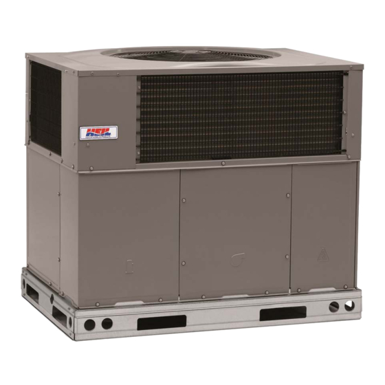
Fig. 1 - - Unit PGD4, PGS4, WPG4
NOTE TO EQUIPMENT OWNER:
NOTE TO INSTALLER:
This manual must be left with the equipment owner.
Specifications are subject to change without notice.
INSTALLATION INFORMATION
Date Installed________________________________
DEALERSHIP CONTACT INFORMATION
Company Name_______________________________
Address______________________________________
_____________________________________________
Phone Number _______________________________
Technician Name _____________________________
_____________________________________________
A09034
46202200205
04/2019
Advertisement
Table of Contents


Need help?
Do you have a question about the PGD4 and is the answer not in the manual?
Questions and answers