Table of Contents
Advertisement
Quick Links
NOTE:
Read the entire instruction manual before starting the
installation.
DLFBHC
INSTALLATION INSTRUCTIONS
Cassette Ductless System − Sizes 12 − 24
Specifications subject to change without notice.
TABLE OF CONTENTS
. . . . . . . . . . . . . . . . . . . . . . . . . . . . . . . . . . . . . . . . . . .
. . . . . . . . . . . . . . . . . . . . . . . . . . . . . . .
. . . . . . . . . . . . . . . . . . . . . . . . . . . . . . . .
. . . . . . . . . . . . . . . . . . . . . . . . . . . . . . .
. . . . . . . . . . . . . . . . . . . . . . . . . . . . . . . . . . . .
. . . . . . . . . . . . . . . . . . . . . . . . . . . . . . . . . . .
. . . . . . . . . . . . . . . . . . . . . . . . . . . . . . . . . . . . . . . . . . . .
. . . . . . . . . . . . . . . . . . . . . . . . . . . . . . . . . .
. . . . . . . . . . . . . . . . . . . . . . . . . . . . .
. . . . . . . . . . . . . . . . . . . . . . . . . . .
. . . . . . . . . . . . . . . . . . . . . . . . . . . . .
PAGE
2
3
4
5
7
8
8
11
11
13
14
Advertisement
Table of Contents

Related Manuals for HEIL DLFBHC12K1A


Summary of Contents for HEIL DLFBHC12K1A
-
Page 1: Table Of Contents
DLFBHC INSTALLATION INSTRUCTIONS Cassette Ductless System − Sizes 12 − 24 TABLE OF CONTENTS PAGE SAFETY CONSIDERATIONS ......PARTS LIST . -
Page 2: Safety Considerations
SAFETY CONSIDERATIONS WARNING Installing, starting up, and servicing air−conditioning equipment can be hazardous due to system pressures, electrical components, and EXPLOSION HAZARD equipment location (roofs, elevated structures, etc.). Failure to follow this warning could Only trained, qualified installers and service mechanics should install, result in death, serious personal injury, start−up, and service this equipment. -
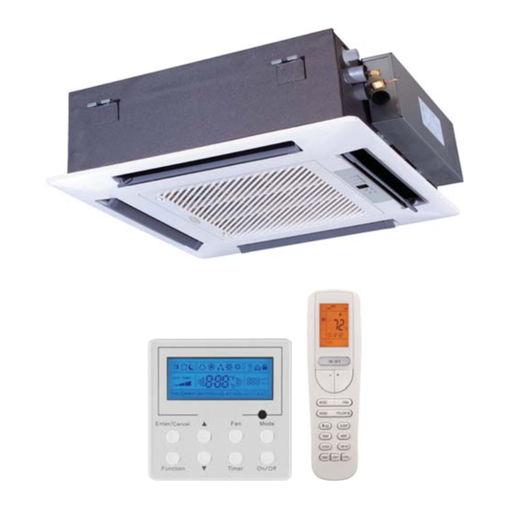
Page 3: Parts List
Connection wire of wired control Wired controller The following units are covered in these installation instructions. Table 2—Indoor Units Description kBTUh V-Ph-Hz Indoor Model Number Grille Model Number 208/230-1-60 DLFBHC12K1A DLFBHC01K1A Cassette 208/230-1-60 DLFBHC18K1A DLFBHC01K1A 208/230-1-60 DLFBHC24K1A DLFBHC02K1A 328 014525201... -
Page 4: System Requirements
SYSTEM REQUIREMENTS Allow sufficient space for airflow and servicing unit. See Fig. 4 for minimum required distances between unit and walls or ceilings. Piping IMPORTANT: Both refrigerant lines must be insulated separately. S Table 3 lists the pipe sizes for the indoor unit. Refer to the outdoor unit installation instructions for other allowed piping lengths and refrigerant information. -
Page 5: Dimensions − Indoor
DIMENSIONS − INDOOR Fig. 2 - Size 12 and 18 Cassette Dimensions Table 4—Dimensions Indoor SYSTEM SIZE Height (H) in (cm) 9.1 (23.1) 9.1 (23.1) Width (W) in (cm) 22.4 (56.9) 22.4 (56.9) Depth (D) in (cm) 22.4 (56.9) 22.4 (56.9) Weight-Net lbs(kgs) 39.7 (18) - Page 6 DIMENSIONS − INDOOR (CONTINUED) Fig. 3 - Size 24 Cassette Dimensions Table 5—Dimensions SYSTEM SIZE Height (H) In (CM) 9.4 (23.9) Width (W) In (CM) 33.1 (84.1) Depth (D) In (CM) 33.1 (84.1) Weight-Net Lbs (Kgs) 61.7 (28) 328 014525201 Specifications subject to change without notice.
-
Page 7: Clearances − Indoor
CLEARANCES − INDOOR Fig. 4 - Cassette Clearance 328 014525201 Specifications subject to change without notice. -
Page 8: Installation Tips
INSTALLATION TIPS IMPORTANT: The drilling of holes in the ceiling must be done by the professional personnel. Ideal installation locations include: Installation stands for main body of the unit Indoor Unit S A location where there are no obstacles near inlet and outlet area. S A location which can bear the weight of indoor unit. - Page 9 CONNECTION OF THE REFRIGERANT PIPE INSTRUCTION Connection of the Refrigerant Pipe The slant gradient of the attached drain hose should be within 3 in. (75 mm) so that the drain hole does not have to endure unnecessary outside When connecting the pipe to the unit or backout from the unit, use both force.
- Page 10 NOTE: The power cord reference power cord standard recommending table. (1.) Improper screwing of the screws may cause issues as shown in Fig. 16. Air leak Air leak from ceiling Water condensatation, water drop Fig. 16 - Improper Screwing Fig. 14 - Power cord (2.) If a gap still exists between the ceiling and decoration Install the panel panel after tightening the screws, readjust the height of...
-
Page 11: Electrical Data
ELECTRICAL DATA Table 6—Electrical Data INDOOR FAN HIGH WALL UNIT MAX FUSE CB AMP SIZE V-Ph-Hz 0.18 1/72 Refer to outdoor unit installation instructions – 208/230-1-60 0.18 1/72 Indoor unit powered by the outdoor unit. Sizes 18 to 42 and powered by the Branch Box sizes 48 and 56. 0.43 1/20 LEGEND... - Page 12 12K to 24K 208/230V Indoor unit tubing Flare nut Piping A150769 Fig. 24 - Align Pipe Center L2 S h. Connect both the liquid and gas piping to the indoor unit i. Tighten the flare nut using a torque wrench as specified in Table Table 8—Tightening Torque TIGHTENING TORQUE PIPE DIAMETER INCH...
-
Page 13: Start−Up
START−UP SYSTEM CHECKS Test Operation 1. Conceal the tubing where possible. Perform a test operation after completing gas leak and electrical safety 2. Make sure that the drain tube slopes downward along its entire check (see Fig. 26). length. 3. Ensure all tubing and connections are properly insulated. 4. -
Page 14: Troubleshooting
TROUBLESHOOTING This unit has on−board diagnostics. Error codes are displayed on the wired remote controller and the outdoor unit microprocessor board with colored LED lights. Table 9 explains the error codes on both. Table 9—Malfunction Status Table Outdoor Multi−zone Sizes 18 & 24 INDOOR MALFUNCTION NAME MALFUNCTION TYPE... - Page 15 TROUBLESHOOTING (CON’T) This unit has on−board diagnostics. Error codes are displayed on the wired remote controller and the outdoor unit microprocessor board with colored LED lights. Table 10 explains the error codes on both. Table 10—Malfunction Status Table Outdoor Multi−zone Sizes 30, 36, & 42 THE INDICATOR DISPLAY INDOOR NAME OF MALFUNCTION...
- Page 16 TROUBLESHOOTING (CON’T) This unit has on−board diagnostics. Error codes are displayed on the wired remote controller and the outdoor unit microprocessor board with colored LED lights. Table 11 explains the error codes on both. Table 11—Malfunction Status Table Outdoor Multi−zone Sizes 48−56 MAIN CONTROL DISPLAY FOR OUTDOOR UNIT INDOOR UNIT TESTING...
-
Page 17: Branch Boxes
TROUBLESHOOTING (CON’T) This unit has on−board diagnostics. Error codes are displayed on the wired remote controller and the outdoor unit microprocessor board with colored LED lights. Table 12 explains the error codes on both. Table 12—Malfunction Status Table Outdoor Multi−zone Sizes 48−56 TESTING MAIN CONTROL DISPLAY FOR OUTDOOR UNIT INDOOR UNIT... - Page 18 Copyright 2016 International Comfort Products Lewisburg, Tennessee 37091 USA 328 014525201 Specifications subject to change without notice.
Need help?
Do you have a question about the DLFBHC12K1A and is the answer not in the manual?
Questions and answers