
Related Manuals for Magic-Pro MP-VIP4

Summary of Contents for Magic-Pro MP-VIP4
- Page 1 MP-VIP4 Motherboard User’s Manual Product Name: MP-VIP4 Manual Revision: English,3.00 Release Date: Feb 10, 1999...
- Page 2 All trademarks, product names or brand names appearing in this document are registered property of their respective owners. Copyright Magic-Pro Computer Co., LTD. All rights reserved Author : Raymond Liu Printed in Taiwan...
-
Page 3: Table Of Contents
Contents Chapter 1: Introduction --------------------------------------- 1 Features ------------------------------------------------------------------------- 1 CPU ------------------------------------------------------------------------ 1 Chipset -------------------------------------------------------------------- 1 L2 Cache ------------------------------------------------------------------ 1 Main Memory ----------------------------------------------------------- 1 BIOS ------------------------------------------------------------------------ 2 I/O Function ------------------------------------------------------------- 2 Other Functions --------------------------------------------------------- 2 Mainboard Setting for Pentium MMX-200----------------------------- 3 Chapter 2: Hardware Setup ---------------------------------- 4 CPU VCORE Voltage Setting---------------------------------------------- 4 JP3: CPU VCore Voltage Setting ----------------------------------- 4... - Page 4 JP7, JP8: Chipset Clock Settings ---------------------------------- 13 IDE LED Activity Light: (J1 pin1Ð4)------------------------------ 14 Infrared Port Module Connector (J1 pin6Ð10) ----------------- 14 J1 pin12, 13: ATX Power Button ---------------------------------- 14 J1 pin14, 15: Reserved ----------------------------------------------- 14 Speaker Connector (J2 pin1Ð4) ------------------------------------ 14 Reset Switch (J2 pin5, 6)--------------------------------------------- 14 Power LED and Keylock Switch (J2 pin8Ð12)------------------ 14 Turbo LED (J2 pin14, 15)-------------------------------------------- 15...
-
Page 5: Chapter 1: Introduction
Chapter 1 Introduction Features 1. Supports Intel Pentium P54C/MMX (P55C) CPUs at 133 ~ 233 MHz; 2. Supports Cyrix/IBM 6x86(L) CPUs at PR133 + ~ PR250 + MHz and 6x86MX/MII CPUs at PR166 + ~ PR350 + MHz; 3. Supports AMD K5: PR133 ~ PR200MHz, AMD K6: 166 ~ 300MHz, and AMD K6-2: 250 ~ 400MHz;... -
Page 6: Bios
BIOS 1. AWARD Plug and Play BIOS; 2. Supports Advanced Power Management Function; 3. Flash Memory for easy upgrade. I/O Function 1. Integrated USB (Universal Serial Bus) controller with two USB ports; 2. Supports 2 IDE channels with 4IDE devices (including 120MB IDE floppy);... -
Page 7: Mainboard Setting For Pentium Mmx-200
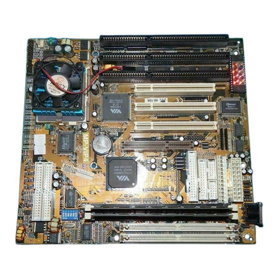
PCI1 VT82C586B ISA3 ISA2 ISA1 Clock Pipelined SRAM MMX-200 CPU Pipelined IDE1 SRAM IDE2 HD/LED PWR/SW RESET KEYLOCK T/LED Figure 1–1. MP-VIP4 Motherboard Layout Note: Double Check JP1, JP6 ~ JP8 if system can not be boot up. Introduction 3... -
Page 8: Chapter 2: Hardware Setup
Chapter 2 Hardware Setup CPU V Voltage Setting CORE JP3: CPU V Voltage Setting Core Core Core Core Core Voltage Voltage Voltage Voltage 2.8V 3.2V 2.0V 2.4V MMX, 6x86L K6Ð233 2.9V 3.3V 2.1V 2.5V K6Ð166/200 IDT C6 6x86MX (MII) 2.2V K6-266 2.6V 3.0V... -
Page 9: Agp Driver For Win95 Installation
Note: 1. Refer to the table above to choose the correct voltage for the CPU everytime that you install a CPU. 2. Make sure that your JP3 is matched with the CPU voltage, otherwise will damage the CPU or make the system unstable. 3. -
Page 10: Intel Pentium Mmxð166/200/233 Cpus
ÒHKEY_LOCAL_MACHINES\System\CurrentControlSet\ Services\VxDÓ. Follow the below procedure to check if the AGP driver is capable to activate: 1. Activate ÒControl Panel,Ó 2. Click ÒDirectX,Ó 3. Click ÒDirectDraw,Ó and 4. Check if there are some values in ÒBitÓ and ÒOverlays.Ó If there are some values, the AGP is able to activate. Intel Pentium MMX–166/200/233 CPUs MMX–166 MMX–200... -
Page 11: Amd K6 Cpu Settings
AMD K6 CPU Settings AMD K6 – 166/200/233/266/300 and K6-2 266 CPUs K6-2-266 K6–166 K6–200 K6–233 K6–300 K6–266 K6–166 K6-2-266 K6–233 K6–200 K6–266/300 (2.9V) (2.2V) (3.2V) AMD K6 CPUs Figure 2–2. CPU Type Configuration Note: 1. K6–233 CPU is 3.2V. Please check its spec before using it. -
Page 12: Amd K6-2 Ð 250/300/333/350/380/400 Cpu Settings
AMD K6-2 – 250/300/333/350/380/400 CPU Settings K6-2–250 K6-2–333 K6-2–300 K6-2–350 (100MHz x 2.5) (95MHz x 3.5) (100MHz x 3.0) (100MHz x 3.5) AMD K6-2 (2.2V) K6-2–380 K6-2–400 CPUs (95MHz x 4.0) (100MHz x 4.0) Figure 2–3. CPU Type Configuration Note: 1. JP1 and JP6 are used to set the SDRAM clock the same as the AGP clock (66MHz), however in the 100MHz Bus Clock environment, make sure that the SDRAM is compliant with PC-100... -
Page 13: Cyrix/Ibm 6X86Mx Ð Pr200/233/266 Cpus
Cyrix/IBM 6x86MX – PR200/233/266 CPUs MII – 300/333/350 CPUs 6x86MX–PR200 6x86MX–PR233 6x86MX–PR266 (66MHz x2.5) (66MHz x 3.0) (75MHz x 3.0) 6x86MX–PR200 6x86MX–PR233 6x86MX–PR266 (75MHz x 2.0) (75MHz x2.5) (83MHz x 2.5) JP1* Cyrix/IBM (2.9V) 6x86MX/MII CPUs *JP6 For 66/75MHz For 83MHz For 100MHz MII–300 MII–333... -
Page 14: Idt C6 Ð 200/225 Cpus
IDT C6 – 200/225 CPUs C6-200 C6-225 IDT C6 (3.3V) CPUs Figure 2–5. CPU Type Configuration Intel Pentium/AMD K5 – 133/166/200 CPUs Pentium–166 Pentium–200 Pentium–133 K5–PR166 K5–PR200 K5–PR133 (3.5V) Pentium/K5 CPUs Figure 2–6. CPU Type Configuration... -
Page 15: System Memory Configuration
System Memory Configuration This Apollo MVP3 motherboard supports 72-pin SIMMs and 168pin DIMMs (3.3V unbuffered type) of 4MB, 8MB, 16MB, or 32MB to form a memory size between 4MB to 1GB (total of 6 rows are supported). The Apollo MVP3 chipset supports ÒTable FreeÓ configuration so that DRAM module can be installed at any capacity. -
Page 16: Jp17, Jp18: Cpu Dual/Single Voltage Select
JP17, JP18: CPU Dual/Single Voltage Select JP17/JP18 CPU Type Single Pentium P54C, K5, Votage 6x86, IDT Dual MMX, 6x86L/6x86MX, Votage K6, K6-2, MII Note: Wrong setting of JP17/JP18 will damage the CPU. Please double check before powering on the system. SW1: 4~6: Bus Ratio Select SW1: 1~3: CPU Clock Setting Set the SW1 jumper according to your CPU Bus Ratio and... -
Page 17: Jp1, Jp6: Sdram Clock Setting
JP1, JP6: SDRAM Clock Setting SDRAM Note Clock SDRAM clock AGP Clock synchronous with (66MHz) AGP clock. SDRAM clock CPU Clock synchronous with (default) CPU clock. Note: The default settings for JP1 and JP6 are set the way that SDRAM clock is synchronized with CPU clock, if CPU is 100MHz clock and SDRAM can't comply with CPU clock, then, use the “SDRAM asynchronous with CPU”... -
Page 18: Ide Led Activity Light: (J1 Pin1Ð4)
IDE LED Activity Light: (J1 pin1–4) This connector connects to the hard disk activity indicator light on the case. Infrared Port Module Connector (J1 pin6–10) The system board provides a 5-pin infrared connectorÑIR1 as an optional module for wireless transmitting and receiving. -
Page 19: Turbo Led (J2 Pin14, 15)
Turbo LED (J2 pin14, 15) Connect the caseÕs turbo LED to this connector. Power HD/LED Button RESET KEYLOCK T/LED Power Button HD/LED RESET KEYLOCK T/LED Power Button HD/LED IR CON 9 10 12 13 14 15 9 10 11 12 14 15 Power Turbo... -
Page 20: Usb: Usb Connector
USB: USB Connector This jumper connects to the USB cable to provide USB device. 16 15 D1 + D1– COM1/2 D0 + D0– MS1 Top View COM1/2 (Top View) Mouse Clock Mouse Data N.C. N.C. -
Page 21: J1 Switch Signal Summary
J1 Switch Signal Summary Signal Description HDD LED Connector HDD LED Signal HDD LED Signal N.C. No Connection Infrared Transmit Signal Infrared Connector Infrared Receive Signal (low speed) Infrared Receive Signal (high speed) No Connection Power Button (ATX ATX Power Button Power) N.C. -
Page 22: J2 Switch Signal Summary
J2 Switch Signal Summary Signal Description Speaker Signal Speaker Connector No Connection Ground Reset Switch Reset Signal Ground N.C. No Connection Power LED Connector No Connection Ground Keylock Connector Keylock Signal N.C. No Connection Turbo LED Connector Turbo LED Connector Ground... -
Page 23: Chapter 3: Bios Setup
Chapter 3 Award BIOS Setup This VIA MVP3 motherboard comes with the AWARD BIOS from AWARD Software Inc. Enter the Award BIOS programÕs Main Menu as follows: 1. Turn on or reboot the system. After a series of diagnostic checks, the following message will appear: PRESS <DEL>... -
Page 24: Standard Cmos Setup
3. Using one of the arrows on your keyboard to select an option and press <Enter>. Modify the system parameters to reflect the options installed in the system. 4. You may return to the Main Menu anytime by press <ESC> . 5. - Page 25 A short description of screen options follows: Date (mm:dd:yy) Set the current date and time. Time (hh:mm:ss) This field records the specifications Primary (Secondary) for all non-SCSI hard disk drives Master/Slave installed in your system. Refer to the respective documentation on how to install the drivers.
-
Page 26: Bios Features Setup
BIOS Features Setup BIOS Features Setup allows you to improve your system performance or set up some system features according to your preference. Run the BIOS Features Setup as follows: 1. Choose ÒBIOS FEATURES SETUPÓ from the Main Menu and a screen with a list of options appears. ROM PCI/ISA BIOS BIOS FEATURES SETUP AWARD SOFTWARE, INC. - Page 27 A short description of screen options follows: Virus Warning Enabled: Activates automatically when the system boots up causing a warning message to appear if there is anything attempts to access the boot sector or hard disk partition table. Disabled: No warning message will appear when there is something attempts to access the boot sector or...
- Page 28 Boot Sequence Default is ÒA, C, SCSIÓ. This option determines which drive to look for first for an operating system. Swap Floppy Drive Choose Enabled or Disabled (default). This option swaps floppy drive assignments when it is enabled. Boot Up Floppy Enabled (default): During POST, Seek BIOS checks the track number of the...
-
Page 29: Chipset Features Setup
PCI/VGA palette Choose Enabled or Disabled (default). It determines whether the Snoop MPEG ISA cards can work with PCI/VGA or not. Video BIOS Enabled (default): Map the VGA Shadow BIOS to system RAM. Disabled: DonÕt map the VGA BIOS to system RAM. C8000-CBFFF to These options are used to shadow DC000-DFFF... - Page 30 ROM PCI/ISA BIOS CHIPSET FEATURES SETUP AWARD SOFTWARE, INC. Bank 0/1 DRAM Timing : FP/EDO 70ns Bank 2/3 DRAM Timing : FP/EDO 70ns Bank 4/5 DRAM Timing : FP/EDO 70ns SDRAM Cycle Length DRAM Read Pipeline : Enabled Cache Rd+CPU Wt Pipeline : Enabled Cache Timing : Fast...
- Page 31 AGP Aperture Size Choose 4 , 8, 16, 32, 64 (default), 128, or 256 MB. Memory mapped and (MB) graphics data structures can reside in a Graphics Aperture. This area is like a linear buffer. BIOS will auto report the starting address of this buffer to the O.S.
-
Page 32: Power Management Setup
Power Management Setup Power Management Setup sets the systemÕs power saving functions. 1. Choose ÒPOWER MANAGEMENT SETUPÓ from the Main Menu and a screen with a list of options appears. ROM PCI/ISA BIOS POWER MANAGEMENT SETUP AWARD SOFTWARE, INC. Primary INTR : ON Power Management : User Define... - Page 33 Video Off Method Choose Blank , DPMS, or V/H Sync+Blank (default). You can chose either DPMS or V/H Sync+Blank when the monitor has the Green function. You need to choose Blank when the monitor does not have the Green function. Note: Some VGA cards don’t allow V/H Sync to be turned...
-
Page 34: Pnp/Pci Configuration Setup
LPT & COM Use the default setting. HDD & FDD Use the default setting. DMA/Master Use the default setting. Modem Ring Enabled: Wake up the system Resume from ring signal. Disabled: (default) Ring signal can not wake up the system. RTC Alarm Enabled: Wake up the system at Resume... - Page 35 ROM PCI/ISA BIOS PNP/PCI CONFIGURATION AWARD SOFTWARE, INC. PNP OS Installed : No CPU to PCI Write Buffer : Enabled Resources Controlled By : Manual PCI Dynamic Bursting : Enabled Reset Configuration Data : Disabled PCI Master 0 WS Write : Enabled ACPI I/O Device Node : Enabled...
- Page 36 Reset Choose Enabled or Disabled (default). Disabled means to retain Configuration Data PnP configuration data in BIOS and Enabled means to reset PnP configuration data in BIOS. ACPI I/O Device Choose Disabled (default) or Node Enabled. Enabled is only used when the ACPI device is installed on to the system.
-
Page 37: Load Setup Defaults
Load Setup Defaults Load Setup Defaults option loads the default system values to the system configuration fields. If the CMOS is corrupted the defaults are loaded automatically. Choose this option and the following message appears: “Load Setup Defaults (Y/N)? N” To use the Setup defaults, change the prompt to ÒYÓ... -
Page 38: Integrated Peripherals
Integrated Peripherals Integrated Peripherals option changes the values of the chipset registers. These registers control system options in the computer. 1. Choose ÒINTEGRATED PERIPHERALSÓ from the Main Menu and a screen with a list of options appears. ROM PCI/ISA BIOS INTEGRATED PERIPHERALS AWARD SOFTWARE, INC. - Page 39 IDE HDD Block Choose Enabled (default) or Disabled. If your hard disk size is Mode larger than 540MB, choose Enabled, and, if you are using the IDE HDD Auto Detection option, the BIOS will choose this option automatically. (Note: Some old HDD models donÕt provide this feature.) IDE Primary...
- Page 40 UART2 Mode Choose Standard (default), HPSIR, or ASKIR. IR Function Choose Half (default), or Full. Duplex Half: DoesnÕt transmit and receive activities at the same time. Full: Transmit and receive activities at the same time. RxD, TxD Active Choose Hi/Hi, Hi/Lo, Lo/Hi, or Lo/Lo (default).
-
Page 41: Supervisor/User Password
Parallel Port EPP Choose EPP1.7 (default) or EPP1.9. EPP1.9 supports hardware Type handshake. This setting is dependent on your EPP device. Note: The above 2 options will not be displayed unless the EPP/ECP function is selected. 3. Press <ESC> and follow the screen instructions to save or disregard your settings. -
Page 42: Ide Hdd Auto Detection
7. Move the cursor to Save & Exit Setup to save the option you did, otherwise the old password will still be there when you turn on your machine next time. 8. Press <ESC> to exit to the Main Menu. Note: If you forget or lose the password, the only way to access the system is to clear the CMOS RAM by... -
Page 43: Exit Without Saving
Exit Without Saving Exit Without Saving allows you to exit the Setup utility without saving the modifications that you have specified. Highlight this option on the Main Menu and the following message appears: Quit Without Saving (Y/N)? N You may change the prompt to ÒYÓ and press <Enter> key to leave this option.
Need help?
Do you have a question about the MP-VIP4 and is the answer not in the manual?
Questions and answers