Table of Contents
Advertisement
Quick Links
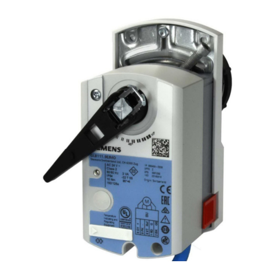
Acvatix™
Rotary Actuator for Ball Valves Modbus RTU
G..B111.9E/MO
30
A6V10881143_en--_e
2021-06-17
Rotary actuator for ball valves 10 Nm with Modbus communication
●
GDB111.9E/MO with 5 Nm nominal torque
●
GLB111.9E/MO with 10 Nm nominal torque
●
Operating voltage AC 24 V
●
For air-handling units (AHU) and other heating / cooling applications
●
Modbus RTU communication
●
UL listed
●
For 2-port and 3-port control ball valves, internally threaded connections
(VAI61.. and VBI61..) or externally threaded connections (VAG61.. and
VBG61..), DN15 to DN50
●
For 6-port control ball valve, externally threaded connections (VWG41..),
DN20
Smart Infrastructure
Advertisement
Table of Contents

Related Manuals for Siemens Acvatix G B111.9E/MO Series


Summary of Contents for Siemens Acvatix G B111.9E/MO Series
- Page 1 Acvatix™ Rotary Actuator for Ball Valves Modbus RTU G..B111.9E/MO Rotary actuator for ball valves 10 Nm with Modbus communication ● GDB111.9E/MO with 5 Nm nominal torque ● GLB111.9E/MO with 10 Nm nominal torque ● Operating voltage AC 24 V ● For air-handling units (AHU) and other heating / cooling applications ●...
-
Page 2: Type Summary
Spare parts Ordering (Example) Product no. Stock no. Description Amount GLB111.9E/MO S55499-D206 Rotary actuator for Ball Valves with Modbus RTU communication Accessories Type Stock no. Description ALJ100 S55846-Z115 Temperature adapter for ball valves 2 / 14 Siemens A6V10881143_en--_e Smart Infrastructure 2021-06-17... -
Page 3: Equipment Combinations
Equipment combinations The rotary actuators are suitable for operation of the following Siemens ball valves: VA..61.. 2-port and VB..61.. 3-port control ball valves Control ball valves with: G..B..9E.. internal threads external threads G..B p p ‒ ‒ VAG61.15.. G 1 B 1…6.3... - Page 4 3. If the button is pressed within these 3s, the reset is cancelled. 4. After those 3s LED shines (reset), then green (start-up). Related documents such as environmental declarations, CE declarations, etc., can be downloaded at the following Internet address: http://siemens.com/bt/download 4 / 14 Siemens A6V10881143_en--_e Smart Infrastructure 2021-06-17...
- Page 5 1. Enter addressing mode 2. Set 1-digits: Press button 5-times LED flashes green per button press 3. Store address: press button until LED shines address is stored and displayed 1x for confirmation 5 / 14 A6V10881143_en--_e Siemens 2021-06-17 Smart Infrastructure...
-
Page 6: Modbus Registers
2 = 1-8-N-1 / 3 = 1-8-N-2 Bus Termination 0 = Off / 1 = On Bus Conf. Command 0 = Ready / 1 = Load / 2 = Discard Status See below 6 / 14 Siemens A6V10881143_en--_e Smart Infrastructure 2021-06-17... -
Page 7: Supported Function Codes
Supported function codes Function codes 03 (0x03) Read Holding Registers 04 (0x04) Read Input Registers 06 (0x06) Write Single Register 16 (0x10) Write Multiple registers (Limitation: Max. 120 registers within one message) 7 / 14 A6V10881143_en--_e Siemens 2021-06-17 Smart Infrastructure... - Page 8 Mounting positions, cf. mounting instr. A6V10920701 Related documents such as environmental declarations, CE declarations, etc., can be downloaded at the following internet address: http://siemens.com/bt/download Engineering GDB..9E.. actuators may only be used at medium temperatures > 0 °C. If condensation occurs at the mounting site, the use of the temperature adapter ALJ100 is recommended in order to protect the actuator.
- Page 9 New value (ex.) MacAddress Baudrate 0 = auto 1 = 9600 Transmission Mode 0 = 1-8-E-1 3 = 1-8-N-2 Termination 0 = Off 0 = Off BusConfigCmd 0 = Ready 1 = Load 9 / 14 A6V10881143_en--_e Siemens 2021-06-17 Smart Infrastructure...
- Page 10 Comply with all local and currently applicable laws and regulations. Warranty Technical data on specific applications are valid only together with Siemens products listed under "Equipment combinations". Siemens rejects any and all warranties in the event that third-party products are used.
-
Page 11: Technical Data
Termination 120 Ω electronically switchable Default: Off Degree of protection Degree of protection Degree of protection acc. to EN 60529 IP54 (see mounting instruction) Safety class Safety class acc. to EN 60730 11 / 14 A6V10881143_en--_e Siemens 2021-06-17 Smart Infrastructure... - Page 12 Dimensions / Weight GLB111.9E/MO GDB111.9E/MO Weight Without packaging 0,9 kg 0,9 kg Dimensions 88 x 112 x 143 mm 88 x 112 x 143 mm The documents can be downloaded from http://siemens.com/bt/download 12 / 14 Siemens A6V10881143_en--_e Smart Infrastructure 2021-06-17...
- Page 13 100 % of the time. Dimensions Actuator Dimensions in mm Minimum clearance from ceiling or wall for mounting, = > 100 mm connection, operation, maintenance etc. = > 200 mm 13 / 14 A6V10881143_en--_e Siemens 2021-06-17 Smart Infrastructure...
- Page 14 Temperature adapter (optional) 23.5 Revision numbers Type Valid from rev. no. GLB111.9E/MO GDB111.9E/MO Issued by © Siemens Switzerland Ltd, 2021 Technical specifications and availability subject to change without notice. Siemens Switzerland Ltd Smart Infrastructure Global Headquarters Theilerstrasse 1a 6300 Zug Switzerland Tel.
Need help?
Do you have a question about the Acvatix G B111.9E/MO Series and is the answer not in the manual?
Questions and answers