Table of Contents
Advertisement
Quick Links
DW9L Series
National High-tech Enterprise/National Standard Drafting Unit
Edition and modification record
Date
Version
Modify content
First File
2022.01.10
F/0
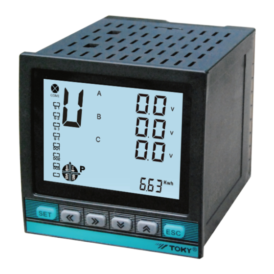
DW9L Series 3 Phase Energy Meter
Operation Manual
Toky Electrical Co., Ltd
Hot line:400-0760-168
Site:http://www.toky.com.cn
KKDW9L-F02E-A/0-20220110
Advertisement
Table of Contents

Summary of Contents for Toky DW9L Series
- Page 1 DW9L Series National High-tech Enterprise/National Standard Drafting Unit Edition and modification record Date Version Modify content First File 2022.01.10 DW9L Series 3 Phase Energy Meter Operation Manual Toky Electrical Co., Ltd Hot line:400-0760-168 Site:http://www.toky.com.cn KKDW9L-F02E-A/0-20220110...
- Page 2 Index Thank you for choosing our products. In order to facilitate you to use this instrument safely, correctly and efficiently, please read this manual carefully and pay attention to the following points when using it. 1 Product overview 1.1 This instrument implements relevant national standards 1.2 Features and applications 1.3 Product function list 1.4 Measurement parameters...
-
Page 3: Product Description
I. Product Description 1.3 Function List Function DW9L-RC38 DW9L-IRC38 1.1 The instrument implements relevant national standards 3 phase voltage Grid Frequency DL/T 614-2007 <Multi-function Energy Meter> 3 phase current GB/T 17215.301-2007 <Multifunction Harmonic Meter Special Requirements> Zero phase current GB/T 17215.322-2008 <... -
Page 4: Technical Parameters
III. INSTALLATION AND WIRING II.Technical Parameters Item Performance parameters 3.1 Loading List Network 3 phase 4 wires/ 3 phase 3 wire/ Single phase Meter Mounting brackets Instructions Certification Rated value AC3x220V/380V 1( PC ) 1(Set) 1(PC) 1(PC) Overload Continuous:1.2 times Instantaneous:2 times/2s Voltage Power Consumption <0.6VA (each phase) - Page 5 3.6 Connection Drawing 3.5 Terminal corresponding wiring chart Corresponding Corresponding Input & output 3 phase 4 wires 3 phase 3 wires Category Description terminal number letter directions L(+) Input Optional AC and DC power supply; Uc Ub Power Ia Ib* Ib Ic* Range:AC:85~265V DC:100~240V N(-) Input...
- Page 6 3.7 Power Supply 3.12 Communication Output The instrument has a universal (AC/DC) power input interface. If no special explanation is given, it is a standard product The device has a two-wire RS-485 communication port with terminals labeled A+, B-. High-speed optocoupler isolation and of AC220V power interface.
- Page 7 4.4 26 English letters display method on LED: 4.6 Menu Operation Illustration Because this instrument uses a pen-type liquid crystal, it may not be intuitive when displaying characters. Therefore, when Under user menu status reading ambiguity occurs, please check according to the following form. The characters that appear in the instrument have 1.
- Page 8 4.7 Menu modification example Continued from the front chart 1. Setting the current ratio method When character “ do ” is remote control mode, otherwise it is Alarm mode alarm mode reference "4.9 alarm, transmission parameter comparison chart" Measure state 1st level 1: means international standard unit, K: means 1000 times of Alarm Unit...
- Page 9 4.8 Multi-rate setting instructions 4.9 Alarm output and transmission output parameter 1. The 0, 1, 2, and 3 in the rate menu correspond to Sharp, Peak, Flat, and Valley rates, respectively. Customers can Switch output Switch output Parameter Transmission output(4-20mA)code choose to use Two or more of these rates;...
-
Page 10: Simple Troubleshooting
VII. Communication Protocol Description V. SIMPLE TROUBLESHOOTING 7.1 MODBUS-RTU protocol Problem Reason Solution 7.1.1 MODBUS-RTU communication protocol,adopts RS485 half-duplex communication to check 16-bit CRC.The meter does not return No display after adding Check whether the correct operating voltage is added to the L/+ and N/- terminals of the device Power failed to join the device the check error. - Page 11 7.2.4 CRC code calculation method Return message format from slave response: Bytes Returned information Remark 1.Preset a 16-bit register to hexadecimal FFFF (that is all 1); call this register CRC register; Slave response 2.Compare the first 8-bit binary data (the first byte of the communication message frame) with the lower 8 bits Slave address From slave 01 of the 16-bit CRC register and place the result in the CRC register.
- Page 12 0x4036 Reactive power long 0.001kvarh Fractional harmonic communication address 0x4038 Positive active power long 0x4200 A phase voltage 0th harmonic 0.001kWh 0.01% 0x403a Negative active power long 0x4220 A phase current 0th harmonic 0x403c Positive reactive power long Reserved Expansion 0.001kvarh 0x403e Negative reactive power...
- Page 13 Attched 1: Wiring instructions Transmission parameter address 0x4a00 1st transmission method value Communication ADD Value Display character Instructions No decimal point 3 phase 4 wires connection 0x4a01 1st transmission unit(attached 3) 0X4800 3 phase 3 wires connection 0x4a02 1st transmission high limit value 0x4a03 1st transmission low limit value Attched 2: Communication baud rate...
- Page 14 VIII. DLT645 communication description Continued from the front chart 8.1 Overview Sub-harmonic content rate ① This meter is not designed according to the national grid meter specifications. Therefore, only part of the electrical parameters can be read through the DLT645 protocol. For the specific read parameters, please 1st harmonic of phase A voltage 0x020A0101 refer to the correspondence address table below;...
-
Page 15: Send And Receive
COMMIX software instructions 7. Configure the display mode of sending and receiving data; set to "HEX" display mode; 1. Configure commix software 8. After configuring the above functions, open the serial port; 9. Enter the corresponding request message in the sending window, and the CRC will be automatically added; 10.


Need help?
Do you have a question about the DW9L Series and is the answer not in the manual?
Questions and answers