Table of Contents
Advertisement
Quick Links
SD Series
Sensor Meter User Manual
Features:
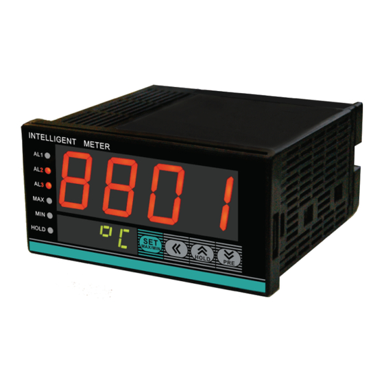
●The red LED display value of real time,maximum & minimum on the upper row,and the green LED
display meansure unit or alarm value.
●The maximum 3 loop alarm output
●Many kinds of linear signal inputs or temperature sensor signals
●Analog analog,enabling conversion and calibration functions of measure range
●RS485 communication and Modbus-RTU protocol
●Power supply 100 ~ 240V AC/DC。
●Isolate DC24V feed output(30mA) 。
●Peak Hold function,to facilitate record maximum, minimum measurement data
●easy to operate, economical and practical.
2.Cable caution:
1)Please use specified compensation wire in the place of TC input;Please use insulated TC if the measured device is heated metal.
2)Please use the cable of lesser resistance in the place of RTD input,and the cable(3 wire) must be no resistance difference,but the total
length is within 5m.
3)In order to avoid the effect of noise,please put the input dignal away from meter cable,power cable,load cable to wiring.
4)In order to reduce the power cables and the load power cables on the effect of this product,please use noise filter in the place
where easy to effect.You must install it on the grounding of the disk if you use the noise filter,and make the wiring to be shortest
between noise filter output side and power connectors.Don`t install fuse and switch on the wiring of noice filter output side,otherwise it
will reduce the effect of noise filter.
5)It takes 5s from input power to output.If there is a place with interlocking actions circuit signal,please use timer relay.
6)Please use twisted pair with a shield for analog output line,to ensure the reliabilty of signal.
7)Please use twisted pair with a shield for remote RS485 communication cable,and deal with the shield on the host side earth,
otherwise it will reduce the effect of noise filter.
8)This product is not the fuse;please set according to rated voltage 250V,rated current 1A if you need;fuse type:relay fuse.
9)Please use the suitable screw force and crimp terminal.
The screw terminal size: M3X8 (with 6.8X6.8 square base)
Recommended tightening torque: 0.4N.m
Proper cables:0.25~1.65mm single cable/multiple core cable
10)Please don`t put the Crimp terminal or bare wire part contact with adjacent connector.
Ⅱ.Model Illustration
SD 8 - l R C 10 B T - C
C:Version
T:Temperature sensor input Blank:Voltage, current input
B: DC 24V auxiliary voltage Blank:No
10: single input without RS485 18:Single input with RS485
A: No alarm C: 2 loop alarm D: 3 loop alarm
Blank: No alarm R: Relay alarm output
I: DC 4-20mA analog output Blank:No alalog
4: 48W*48H 6: 48W*96H 7: 72W*72H 8: 96W*48H
9: 96W*96H 16:80W*160H 80:160W*80H
SD series sensor meter
Ⅲ.Order Information
Model
Signal input
□
SD
-A10
4~20mA/0~10V
□
SD
-A10B
4~20mA/0~10V
□
4~20mA/0~10V
SD
-RC10B
□
SD
-RC18B
4~20mA/0~10V
□
SD
-IRC10B
4~20mA/0~10V
□
SD
-IRC18B
4~20mA/0~10V
□
SD
-A10-T
TC/RTD/mV/RT
□
SD
-RC10B-T
TC/RTD/mV/RT
Ⅳ.Specification
1.Electrical parameters
Sample rate
4SPS
Relay capacity
AC 250V /3A life of rate load>100 thousand times
Power supply
AC/DC 100 ~ 240V (85-265V)
Power consumption
<6VA
Environment
Indoor temperature:0 ~ 50℃ no condensation; Humidity:<85%RH; Altitude<2000m
Storage environment
-10 ~ 60℃, no condensation
KKSDE03-A/0-20151208
Alarm
Auxiliary voltage
Analog output
●
2
●
2
●
2
●
●
2
●
●
2
●
2
The instruction explain instrument settings, connections,name and etc,please read carefully before you use the temperature
controller.
I. Safety Caution
1)If the fault of the product or abnormal system lead to a serious accident, please set the appropriate circuit protection outside.
2)Before the connection completely, please do not power. Otherwise it may result in electric shock, fire, malfunction.
3)Do not use the product out of scope of specifications range. Otherwise, it may result in fire, malfunction.
4)Do not use in places with flammable and explosive gas.
5) Do not touch the site of high voltage power terminal site after power. Otherwise, there is danger of electric shock.
6)Do not disassemble, repair and modify this product. Otherwise,it may result in electric shock, fire, malfunction.
1)This product should not be used in a nuclear plant and medical equipment which associated with human life.
2)Some time,it will happen radio interference when the product uses in home environment.It should take adequate
countermeasures.
3)This product has electric shock protection through improved insulation.And when using the product and connecting,it
subject to compliance with specifications.
4)In order to avoid lighting surge,it should set appropriate surge suppression circuits when the product uses in the
environment where the total cable lengh more than 30 metre.
5)The product uses in disk,and avoid to touch the part of high voltage,please take the necessary measure on the final product.
6)Please observe the precautions in this manual, otherwise there is risk of causing significant harm or accident.
7)Please abserve the regulation when wiring.
8)To prevent to damage the machine and prevent to machine failure, the product is connected with power lines or large capacity input and
output lines and other methods please install proper capacity fuse or other methods of protection circuit.
9)Please don't put metal and wire clastic mixed with this product,otherwise it may lead to electric shock, fire, fault.
10)Please tighten screw torque according to the rules.If not,it may lead to electric shock and fire.
11)In order not to interfere with this products to dissipate heat, please don't plug casing around the cooling vent hole and equipment.
12)Please don`t knock or rub the panel with rigid thing.
13)The readers of this manual should have basic knowledge of electrical,control, computer and communications.
14)The illustration, example of data and screen in this manual is convenient to understand,instead of guaranteeing the result of
the operation.
15)In order to use this product with safety for long-term,regular maintenance is necessary. The life of some parts of the equipments
are by some restrictions, but the performance of some will change for using many years.
16)Without prior notice, the contents of this manual will be change. We hope these is no any loopholes, if you have questions or objections,
please contact us.
1.Installation:
1)This product is used in the following environmental standards.
(IEC61010-1)[Overvoltage categoryⅡ、class of pollution 2]
2)This product is used in the following scope:surrounding environment, temperature, humidity and environmental conditions.
Temperature:0~50℃;Humidity:45~85%RH;Environment condition:Indoor warranty,The altitude is less than 2000m.
3)Please avoid using in the following places:
The place will be dew for changing temperature;with corrosive gases and flammable gas;with vibration and impact;with water, oil, chemicals, smoke and
steam
facilities with Dust, salt, metal powder;and with clutter interference, static electric and magnetic fields, noise;where has air conditioning or heating of air
blowing
directly to the site.
4)On the occasion of the installation, please consider the following before installing several.
In order to protect heat saturated, please ensure adequate ventilation space.
Please consider connections and environment,and ensure that the products below for more than 50mm space.
Please avoid to installed over the machine of the calorific value(Such as heaters, transformer, semiconductor operations, the bulk resistance).
When the surrounding is more than 50℃, please using the force fan or cooling fans.But don't let cold air blowing directly to the product.
Current output
Communication port
Insulation impedance
ESD
Pulse traip anti-interference
Lightning surge
Frequency drop
Dielectric strength
Total weight
Material of case
Material of mark
Power-off data protection
Protection level of panel
Safety Standard
2.Signal parameters
Input
K
K.0
J
E
T
N
B
R
S
Analog output
PT100
CU50
CU100
0 ~ 50mV
●
0 ~ 400Ω
●
0 ~ 10V
4 ~ 20mA
0 ~ 5V
1 ~ 5V
0 ~ 20mA
Warning
Caution
Caution of Install & Connection
1
DC 4 ~ 20mA load < 500Ω,Temperature drift 250PPM
RS485 port Modbus-RTU procotol, maximum input:30 units
Input,output,power cabinet>20MΩ
IEC/EN61000-4-2 Contact ±4KV /Air ±8KV perf.Criteria B
IEC/EN61000-4-4 ±2KV perf.Criteria B
IEC/EN61000-4-5 ±2KV perf.Criteria B
IEC/EN61000-4-29 0% ~ 70% perf.Criteria B
Signal input & output & power 1500VAC 1min,below 60V Low voltage circuit between DC500V,1min
About 400g
The case and panel frame PC/ABS (Flame Class UL94V-0)
PET(F150/F200)
10 years,times of writing:1 million times
IP65(IEC60529)
IEC61010-1 Overvoltage category Ⅱ,pollution level 2,levelⅡ (Enhanced insulation)
Symbol
Range
ratio
0.5%FS±3digits
-50 ~ 1200℃
1℃
0.5%FS±3digits
-50.0 ~ 500.0℃
0.1℃
0.5%FS±3digits
0 ~ 1200℃
1℃
0.5%FS±3digits
1℃
0 ~ 850℃
0.5%FS±2℃
-50 ~ 400℃
1℃
0.5%FS±3digits
-50 ~ 1200℃
1℃
0.5%FS±2℃
600 ~ 1800℃
1℃
0.5%FS±2℃
0 ~ 1600℃
1℃
0.5%FS±2℃
-10 ~ 1600℃
1℃
0.5%FS±3digits
-200.0 ~ 600.0℃
0.1℃
0.5%FS±3℃
-50.0 ~ 150.0℃
0.1℃
0.5%FS±1℃
0.1℃
-50.0 ~ 150.0℃
0.5%FS±3digits
-1999 ~ 9999
0.01%FS
0.5%FS±3digits
-1999 ~ 9999
0.01%FS
0.5%FS±3digits
-1999 ~ 9999
0.01%FS
0.5%FS±3digits
-1999 ~ 9999
0.01%FS
1%FS±3digits
-1999 ~ 9999
0.02%FS
1%FS±3digits
-1999 ~ 9999
0.02%FS
0.5%FS±3digits
-1999 ~ 9999
0.01%FS
3
Input impedance/
Accuracy
Code
auxiliary current
0
>500KΩ
1
>500KΩ
2
>500KΩ
>500KΩ
3
4
>500KΩ
5
>500KΩ
6
>500KΩ
7
>500KΩ
8
>500KΩ
9
0.2mA
10
0.2mA
0.2mA
11
12
>500KΩ
13
0.2mA
14
>500KΩ
15
100Ω
16
>500KΩ
17
>500KΩ
100Ω
18
Advertisement
Table of Contents

Related Manuals for Toky SD Series


Summary of Contents for Toky SD Series
- Page 1 -50 ~ 1200℃ 1℃ >500KΩ 4: 48W*48H 6: 48W*96H 7: 72W*72H 8: 96W*48H 9: 96W*96H 16:80W*160H 80:160W*80H 0.5%FS±2℃ 600 ~ 1800℃ 1℃ >500KΩ SD series sensor meter 0.5%FS±2℃ 0 ~ 1600℃ 1℃ >500KΩ Ⅲ.Order Information 0.5%FS±2℃ -10 ~ 1600℃ 1℃...
- Page 2 3.Isolation diagram Ⅶ.Operation and Menu Direction Power supply 1.Operation of normal menu and shielding menu Press SET key for 3s Analog output MCU(Ⅱ) Relay Communication port Measure input alarm output Press SET key for 3s (Ⅰ) Auxiliary power LCK≠33 LCK=33 “...
- Page 3 Alarm extension function table AL3 start delay(unit:s) DL3A 0~999.9 Alarm mode when show AE1/AE2/AE3 value Whether restrain alarm when power on Alarm control fineness over limit DL3B AL3 close delay(unit:s) 0~999.9 State invariant Do not inhibit Thermocouple cold end compensation method, -1(Auto)...
- Page 4 Address error abnormal answer:( for example, host request address is 0x2101) 0x3104 UNIT Unit setting Refer to symbol table (Page 4) Collocate with DP value to 0x3105 PS Translation correct Slave answer error code read value CAS limit point display value Set the low input point 0x3106 setting...
Need help?
Do you have a question about the SD Series and is the answer not in the manual?
Questions and answers