Advertisement
Quick Links
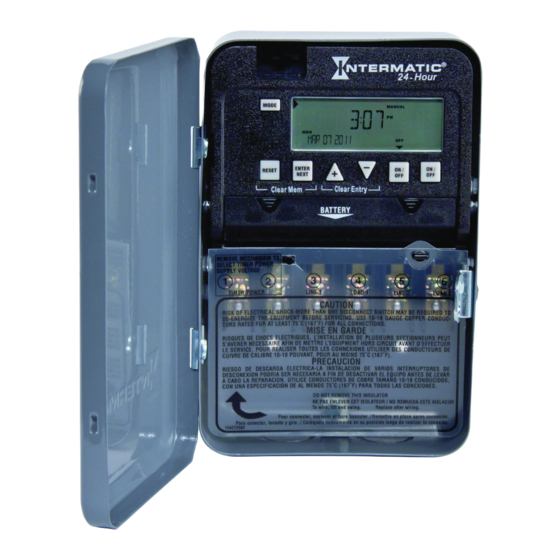
MODEL ET1100 Series
Installation and User Instructions
Description
The Intermatic ET1100 Series Electronic 24-Hour Time Switch
automatically switches loads to a preset daily schedule with to-the-
minute accuracy.
Use the ET1100 series as an ON/OFF timer in applications requir-
ing 24-hour load control such as lighting, air conditioning systems,
pumps, etc. Each load output of the Time Switch can support up to
14 timed ON and 14 timed OFF events per day. The program can be
overridden by pushing the ON/OFF load override button(s).
The ET1100 Series Time Switch is designed to directly switch tung-
sten or ballast loads up to its rating, and inductive or resistive loads
up to 30A at 120, 208, 240, or 277 VAC.
Specifications
Time Switch
•
Input Voltage: 120/208/240/277 VAC, 50/60 Hz
•
Power Consumption: 6.0 watts max.
•
Contact Configuration: SPST (ET1105C), DPST (ET1125C), and
SPDT (ET1115C). See wiring diagrams on next page.
Switch Ratings—ET1105C, ET1125C (per pole)
•
30A Inductive/Resistive: 24/120/208/240/277 VAC, 60 Hz
•
20A Ballast: 120-277 VAC, 60 Hz
•
20A Resistive: 28 VDC
•
5 A Tungsten: 120/240 VAC, 60 Hz
•
1 HP: 120 VAC, 60 Hz
•
2 HP: 240 VAC, 60 Hz
Switch Ratings—ET1115C (NO/NC) Normally Open/Normally Closed Contact
•
20A/10A Inductive/Resistive: 120/208/240/277 VAC, 60 Hz
•
20A/10A Resistive: 28 VDC
•
6A/3A Ballast: 120-277 VAC, 60 Hz
•
5A/3A: 120/240 VAC Tungsten
•
1 HP / ¼ HP: 120 VAC, 60 Hz
•
2 HP / ½ HP: 240 VAC, 60 Hz
Set Points (Events)—Each load output of the Time Switch can support
up to 14 timed ON and 14 timed OFF events per day.
Battery-Powered Clock Operation—2 years minimum (uses 2 AAA
industrial grade alkaline batteries, supplied)
Minimum ON or OFF time—1 minute
Maximum ON or OFF time—23 hours, 59 minutes
Shipping Weight—2.5 lb. (1.1 kg)
Enclosures—Three enclosure options are available.
•
ET11x5C – NEMA 1 indoor metal enclosure
•
ET11x5CR – NEMA 3R indoor/outdoor lockable metal enclosure
•
ET11x5CPD82 – NEMA 3R indoor/outdoor lockable impact resis-
tant polycarbonate enclosure with clear cover
Knockouts—Combination 1/2-3/4 inch size, 1 on back and each side,
2 on bottom
Wire Size—AWG #10 through #18
Electronic 24-Hour
Time Switch
Front View
WARNING–
Risk of Fire or Electric Shock
•
Electrical shock hazard. To avoid fire, shock, or death, disconnect all
power before installing or servicing time switch or connected loads.
•
Follow local electrical and safety codes, National Electric Code (NEC)
and Occupational Safety and Health Act Codes (OSHA).
•
If the power disconnect point is out of sight, lock it in the OFF position
and tag it to prevent unexpected application of power.
•
This time switch must be grounded.
•
Do not exceed maximum current carrying capacity.
•
Always replace the plastic insulator covering the terminal before
powering ON.
Installation Instructions
WARNING: Disconnect the
power to the Time Switch
and the loads before instal-
lation.
1.
Remove the mecha-
nism from the case by
depressing the catch at
the top of the case and
pulling out, as shown.
CAUTION: Do not
touch circuit board
components since
static discharge could damage the microprocessor.
2.
Set voltage selector for desired input voltage.
The timer is shipped with voltage set for 120
VAC. To operate at 208, 240 or 277 VAC, move
the selector switch to the desired setting as
marked on the circuit board. See location A in
Rear View above and detail at the right.
3.
The timer is shipped with DST (Daylight Sav-
ing Time) enabled. To disable DST, insert a jumper at location
marked DST. See location B in Rear View above
and detail at the right.
4.
ET1125C ONLY
—Decide whether you want
to control multiple loads simultaneously (SIM),
independently (IND), or with a 2-second pulse
(PUL) (e.g., for use with mechanically held con-
tactors or bell ringing applications), and make sure the jumper is
positioned accordingly. See location B in Rear View above and
detail at the right. (The unit is shipped with the loads set for IND.)
With Battery
Carryover
B
A
Rear View
Snap out catch
Tilt top forward
Slide down
to remove
battery case
Advertisement

Related Manuals for Intermatic ET1100 Series


Summary of Contents for Intermatic ET1100 Series
-
Page 1: Specifications
Electronic 24-Hour MODEL ET1100 Series Time Switch With Battery Installation and User Instructions Carryover Description The Intermatic ET1100 Series Electronic 24-Hour Time Switch automatically switches loads to a preset daily schedule with to-the- minute accuracy. Use the ET1100 series as an ON/OFF timer in applications requir- ing 24-hour load control such as lighting, air conditioning systems, pumps, etc. Each load output of the Time Switch can support up to 14 timed ON and 14 timed OFF events per day. The program can be overridden by pushing the ON/OFF load override button(s). The ET1100 Series Time Switch is designed to directly switch tung- sten or ballast loads up to its rating, and inductive or resistive loads up to 30A at 120, 208, 240, or 277 VAC. Front View Rear View WARNING–... - Page 2 Mount the enclosure in the desired location using the 3 mount- Insert the wire ends under the proper terminal plates (see wir- ing holes provided. ing diagrams elsewhere on this page) and tighten the screws firmly. Mounting Mounting holes Connect ground wire to grounding terminal at bottom of enclosure. hole Replace the plastic insulator on the retaining post. Remove the battery case by sliding it down as shown by the arrows, then install 2 AAA alkaline batteries. Make sure the batteries are pointing in the direction shown. Verify that the display is ON to make sure the batteries are OK. If the display shows scrambled information, press the RESET Mounting button to clear it up. hole Apply power to the Time Switch. IMPORTANT: Press and hold the ENTER button, then press the Knockouts Knockouts RESET button. The screen will flash 12:00 AM, and timer status is Position at eye level if possible, providing space to the left of Manual Mode.
-
Page 3: Battery Maintenance
LIMITED ONE-YEAR WARRANTY If within one (1) year from the date of purchase, this product fails due to a defect in material or workmanship, Intermatic Incorporated will repair or replace it, at its sole op- tion, free of charge. This warranty is extended to the original household purchaser only and is not transferable. This warranty does not apply to: (a) damage to units caused by accident, dropping or abuse in handling, acts of God or any negligent use;...