Table of Contents
Advertisement
Quick Links
Customer Manual, RBH125 SUPER, RBH185 SUPER
Thank you for choosing a Calyenty Heat pump.
Contents
4. Usage:
4.1 Control panel:
4.2 Start up procedure:
8. Defrosting:
12. General Information:
Calyenty
Swimming Pool Heat Pumps
2.
2.
3.
4.
4.
4.
5.
6.
7.
9.
11
12.
12.
12.
13.
13.
13.
14.
15.
17.
18.
19.
20.
21.
22.
21.
22.
23.
25.
1
Advertisement
Table of Contents
Troubleshooting

Related Manuals for Calyenty RBH125 SUPER

Summary of Contents for Calyenty RBH125 SUPER
-
Page 1: Table Of Contents
1.1 Controller screen: 1.2 Circulation/filtration pump timer/clock: 2. Installation: 2.1 Materials to required to install your Calyenty heat pump, you will need: 2.2 Tools: 2.3 Where to put the heat pump in the hydraulic system: 2.4 Multiple heat pump installations: 2.5 Installation Procedure:... -
Page 2: Quick Reference
Also your warranty will be invalidated if the heat pump is not installed following the procedures in THIS manual exactly. Calyenty continue to explore constant improvements in our products and consequently can be modified without notice; the present pictures in this note or the characteristics which are described are not contractual. -
Page 3: Circulation/Filtration Pump Timer/Clock
1.2 Circulation/filtration pump timer/clock Setting the Time Clock (Guidelines only): Time clock above illustrates auto mode with 12 daytime hours (between 9.00am and 9.00pm), n.b if the top slider switch is in the I position the filter pump will run continuously, and in O will be off. -
Page 4: Installation
2. Installation. Materials. To Install your Calyenty heat pump, you will need: • 3 x 50mm ball valves for the bye-pass. • 2 x 50 mm pressure 90°elbow fittings. • 2 x 50 mm pressure T fittings. • Adequate 50mm pressure tubing (rigid or flexible). -
Page 5: Where To Put The Heat Pump In The Hydraulic System
2.3 Where to put the heat pump in the hydraulic system: The unit is generally installed outdoors (for indoor installation, please consult Calyenty). Install the unit downstream of all pumps and filters and upstream of all chlorinators, ozonizers and chemical pumps. -
Page 6: Installation Procedure
Where more than one heat pump is to be installed it is essential that they are connected to the water system in parallel, see diagram below: 2.5 Installation Procedure:... - Page 7 2. All electrical work should be carried out by a qualified electrician / lampista. 3. Check packaging for obvious signs of damage, before installation begins. Report any damage to Calyenty before installation if you have concerns. 4. Please read the Installation & Operation Manuals carefully before you install or operate the unit.
- Page 8 8. The water is fed through the heat pump using the circulation/filter pump. You will need to identify the return pipe from the filter to the pool (this is often marked RETURN). You will now need to cut into this return plumbing / pipe work of the pool system.
-
Page 9: Connecting To The Electricity Supply
2.6 Connecting to the electricity supply: IMPORTANT: Power supply to the filter pump, and the heat pump, and the switching on and off of both devices must be the same and simultaneous. Using the electrical entry marked “Power Supply” connect the heat pump to the dead side of the filter pump timer clock electricity supply. -
Page 11: Initial Startup
Turn on the power of the unit. Then press the button ON/OFF on the control panel. All Calyenty heat pumps have a variable start delay which can be from just a few seconds to several minutes. This feature reduces load on your power supply which irrespective of the electrical consuming device is always significantly more on start up. - Page 12 4. Using your heat pump: 1. On/off Button Press On/Off button to switch on/off the unit. 2. Set Button This is where you can change various parameters. On commissioning, press this button for five seconds to enter parameter change mode, after five seconds you will see parameter P0 –...
-
Page 13: Backwashing The Pool/Sand Filter
6.1 Maintenance General maintenance: The unit should be maintained by qualified technicians on a regular basis. Ask Calyenty or your local dealer about our maintenance contract options. A professional technician should clean the unit periodically. It is NOT recommended to use a sprinkler to flush the unit. -
Page 14: Troubleshooting
Keep the pump clean. • Check the valves often • 6.2 Troubleshooting The unit would not run. Is the screen of control panel lit? If not, ensure the electrical wires and cables are correctly connected and the power is on. If the screen displays E5, check the water flow. -
Page 15: Error Codes And What To Do
Note: these error codes are likely to occur if temperature of swimming pool water is high and the ambient air is hot. 7. Error codes and what to do: Troubleshooting Guide Problem Possible Reason Solution 1) The water pump is too small. The insufficient water Change to bigger water pump flow results in gas discharge temperature protection. - Page 16 5) The space between inlet water pipe and outlet The space between inlet and outlet water pipe is too narrow, resulting in water water pipes should be no less than 1m shortcircuit. 6) The heat pump is installed in a place where the Improve the ventilation ventilation is not good.
- Page 17 8 Defrost Control Defrost Cut-in Conditions: only when the following two conditions are satisfied: 1.Compressor continuous running time ≥ Defrost Cut-in Time (P2) 2. Evaporator Coil Temperature ≤ Defrost Cut-in Temperature (P3) When the unit enters defrosting mode, the 4-way reversing valve will de- energize, directing the hot gas to the evaporator coil.
-
Page 18: Model Data
9. Model Data:... -
Page 19: Exterior Features
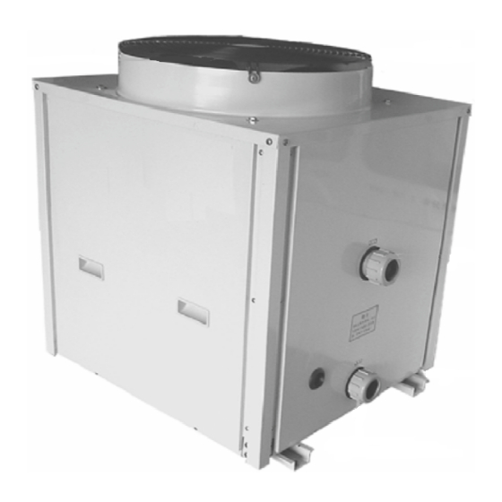
10. Exterior Features. -
Page 20: Interior Features
11. Interior Features. -
Page 21: Features
MORE DURABLE. Extra-wide heat exchanging area-- Except the electrical wiring and water connection area, the surface of Calyenty swimming pool heat pump is for heat exchange between the air and refrigerant in the evaporator. Extra-wide heat exchanging area gets more heat from the air and helps the unit heat the pool more quickly. -
Page 22: Energy Saving Tips
• Please turn the unit off during the winter and drain out all the water by removing the drain plug. We recommend that you cover the machine with a Calyenty winter cover. • Use an accurate thermometer to measure the water temperature. A slight temperature difference may cause a considerable difference in energy consumption. -
Page 23: Mounting The Temperature Sensor
“Med Mounting”. Calyenty provide all the components that you need to perform this simple operation. 1. Remove the side panel of the heat pump and you will find the temperature sensor pushed into its standard mounting position in a port at the top of the heat exchanger (the PVC tank). -
Page 25: Warranty
LIMITATION OF LIABILITY: This is the only warranty given by Calyenty. No one is authorized to make any other warranties on Calyenty products, THIS WARRANTY IS IN LIEU OF ALL OTHER WARRANTIES, EXPRESSED OR IMPLIED, INCLUDING BUT NOT LIMITED TO ANY IMPLIED WARRANTIES OF FITNESS FOR A PARTICULAR PURPOSE AND MERCHANTABILITY. - Page 26 0034 972 660467. All returned parts must have a Returned Material Authorization number to be evaluated under the terms of this warranty. We strongly recommend that you take out a Calyenty maintenance contract.
Need help?
Do you have a question about the RBH125 SUPER and is the answer not in the manual?
Questions and answers