
Related Manuals for IDROFOGLIA TURBOCAR J1


Summary of Contents for IDROFOGLIA TURBOCAR J1
- Page 1 TURBOCAR Contents TURBOCAR Name: Models: J1-J2-J3 IDROFOGLIA S.r.l. Via Provinciale, 14 61026 Lunano PU - Italy Tel: +39 0722 700311 - Fax: +39 0722 700309 Website: www.idrofoglia.com Email:staff@idrofoglia.com...
- Page 2 TURBOCAR Contents CONTENTS PAR. DESCRIPTION Contents Parts of the manual Revision Contents Chapter Instruction Manual Revision Date 20/11/2017...
-
Page 3: Table Of Contents
TURBOCAR Contents FOREWORD 1. Purpose of the instruction manual 4 INSTALLATION 2. How to read the instruction manual 1. Checking the material upon 3. Storage of the instruction manual delivery 4. Update of the Instruction Manual 2. Storage and unpacking 5. -
Page 4: Purpose Of The Instruction Manual
Foreword TURBOCAR 1/10 FOREWORD PAR. DESCRIPTION Purpose of the instruction manual 1. PURPOSE OF THE OPERATING AND MAINTENANCE INSTRUCTION MANUAL. We would like to thank you for the trust you have placed in us by purchasing this new turbocar. This Instruction Manual is an integral part of the Machine and has the purpose of providing all the required information for: •... -
Page 5: How To Read The Instruction Manual
Foreword TURBOCAR 2/10 FOREWORD PAR. DESCRIPTION How to read the instruction manual 2. HOW TO READ THE INSTRUCTION MANUAL. The Manual has been divided into independent chapters, each aimed at a specific operator role (INSTALLER, OPERATOR AND MAINTENANCE TECHNICIAN), for whom the skills required to operate safely on the machine have been defined. - Page 6 Foreword TURBOCAR 3/10 PICTURE NUMBERING Each picture is numbered progressively. Numbering consists as follows: Paragraph Chapter Progressive number Fig. 0.2.1 Picture Abbreviation TABLE NUMBERING Each table is numbered progressively. Numbering restarts from “1” at each new section. Numbering consists as follows: Paragraph Chapter Progressive...
-
Page 7: Storage Of The Instruction Manual
Foreword TURBOCAR 4/10 FOREWORD PAR. DESCRIPTION Storage of the instruction manual 3. STORAGE OF THE INSTRUCTION MANUAL. The Instruction Manual must be stored carefully and must be provided with the Machine through all changes of ownership it might have throughout its service life. Preservation must be promoted by handling it with care, with clean hands and by not placing it on dirty surfaces. -
Page 8: Recipients
Foreword TURBOCAR 5/10 FOREWORD PAR. DESCRIPTION Recipients 5. RECIPIENTS The Manual in question should be used by the Installer, the Operator and the Skilled Personnel authorised to perform machine maintenance. It is specified that “OPERATOR” refers to the personnel in charge of operating, adjusting, cleaning, performing routine maintenance on the machine. -
Page 9: Glossary And Pictorials
Foreword TURBOCAR 6/10 FOREWORD PAR. DESCRIPTION Glossary and pictorials 6. GLOSSARY AND PICTORIALS This paragraph lists uncommon terms or however having a meaning other than common. The paragraph below explains the abbreviations and the meaning of the pictorials used to indicate the qualification of the operator and Machine status. - Page 10 Foreword TURBOCAR 7/10 PICTORIALS The descriptions preceded by this symbol contain Very important information/requirements, especially as regards safety. Failure to comply may entail: • dangers for the safety of operators; • loss of the contractual warranty; • disclaimer of manufacturer’s liabilities. SYMBOL DESCRIPTION Machine operator: operator authorised to use the machine (strictly following...
- Page 11 Foreword TURBOCAR 8/10 SAFETY PICTORIALS In the event they should be deteriorated or removed, the buyer is obliged to restore with identical signs. Operators are expressly forbidden to remove or tamper with the signs. SYMBOL DESCRIPTION MAXIMUM PERMITTED TOWING SPEED: placed on the back of the turbocar trolley (if the machine is approved the limit specified on the registration paper/technical annex applies)
- Page 12 Foreword TURBOCAR 9/10 OPERATORS MUST ADHERE TO THE INSTRUCTIONS OF THE MACHINE’S OPERATING MANUAL GENERIC HAZARD: placed on the machine UPPER LIMBS CRUSHING HAZARD: placed near the abutments of the bar joint UPPER LIMBS ENTRAINMENT DRAGGING HAZARD: placed near moving mechanical parts (roller crown gear-gearbox pinion, roller crown gear-sliding bar pinion drive) LOWER LIMBS CRUSHING HAZARD: placed near the...
- Page 13 Foreword TURBOCAR 10/10 PRESSURISED DUCTS HAZARD place near ducts that may be released DIGITAL METRE COUNTER GRAPH: placed near the digital metre counter (only found on machines with VDO metre counter) SUMMARY OF INSTRUCTIONS AND WARNINGS: placed near the turbine, it sums up the basic instructions for turbocar operation (read carefully)
-
Page 14: General Information
General TURBOCAR Information GENERAL INFORMATION PAR. DESCRIPTION Manufacturer’s identification data 1. MANUFACTURER’S IDENTIFICATION DATA MANUFACTURER IDROFOGLIA S.r.l. REGISTERED OFFICE – ACCOUNTS Via Provinciale, 14 61026 Lunano (PU) - Italy SWITCHBOARD Tel.: +39 0722/700311 Fax: +39 0722/700309 CONTACTS Email: staff@idrofoglia.com Website:... -
Page 15: Machine Identification Data And Plates
General TURBOCAR Information GENERAL INFORMATION PAR. DESCRIPTION Machine identification data and plates 2. MACHINE IDENTIFICATION DATA Each machine is identified by a CE plate indelibly marked with the machine’s reference data. This plate must never be removed and must always be kept legible. In the event of damage a duplicate must be requested. - Page 16 General TURBOCAR Information GENERAL INFORMATION PAR. DESCRIPTION Copy of declaration of conformity 3. COPY OF DECLARATION OF CONFORMITY...
-
Page 17: Safety Regulations
General TURBOCAR Information GENERAL INFORMATION PAR. DESCRIPTION Safety regulations 4. SAFETY REGULATIONS The machine has been constructed in compliance with the safety regulations listed below: UNI EN ISO 12100 Safety of machinery – Risk assessment and risk reduction UNI EN ISO 14121-1 Safety of machinery –... -
Page 18: Information On Technical Support
5. INFORMATION ON TECHNICAL SUPPORT AND WARRANTY The machines are covered by warranty as set forth in the general sales conditions. IDROFOGLIA S.r.l. WARRANTY CONDITIONS 1. The Seller guarantees to the Buyer their final products against faults or malfunctions due to defects in constructions or materials. - Page 19 General TURBOCAR Information algae or other types of foreign matter, or if using fuels or oils that are not appropriate for the motor or pumps they are used for. g. In the event the final product is used in places other than agreed, in places that are dusty, brackish, with presence of corrosive substances, high moisture, difficult environmental conditions, low temperature (lower than 0°C) or high temperature (higher than +30°C).
-
Page 20: Description Of The Machine
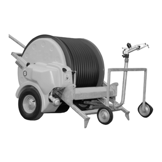
Description TURBOCAR 1/10 Machine DESCRIPTION OF THE MACHINE PAR. DESCRIPTION Operating principle 1. OPERATING PRINCIPLE Hose reel irrigators mainly consists of a long range irrigator, placed on a rubber wheel trolley connected to a polyethylene hose. 1 Winder roller or drum or reel 2 Superstructure or upper frame 3 Hose guide system 4 Long range irrigator... -
Page 21: Main Components
Description TURBOCAR 2/10 Machine DESCRIPTION OF THE MACHINE PAR. DESCRIPTION Main components 2. MAIN COMPONENTS The main components of the TURBOCAR are listed and described below 2.1 TURBINE Device consisting of an impeller that exploits water pressure to move the gearbox for roller rotation, so it reels in the PE hose. - Page 22 Description TURBOCAR 3/10 Machine 2.3 SAFETY DEVICES FOR PTO AND REELING IN OUT OF STOWED POSITION (NOT FITTED IN ALL MODELS) Protection cap for the PTO and the mechanical stop system, in the event the hose should come out of the roller (bar joint). 2.4 MOTION DRIVE TO THE ROLLER VIA CROWN GEAR Transmission between gearbox and roller is direct via pinion keyed onto the output shaft of the gear block and the crown gear welded onto the side of the roller.
- Page 23 Description TURBOCAR 4/10 Machine 2.6 BYPASS TO ADJUST SPEED Device placed near the turbine, on the water system which lets more or less water flow into the turbine, in order to adjust the PE hose reeling in speed. 2.7 GLYCERINE PRESSURE GAUGE Device placed near the turbine, which lets you read the water pressure on the machine.
- Page 24 Description TURBOCAR 5/10 Machine 2.9 FRAME AND WATER SYSTEM WITH INLET The machine consists of a frame and a water system with one inlet, connected the turbine and roller. 2.10 2-WHEEL IRRIGATOR TRAVELLER 2-wheel irrigator trolley connected to the PE hose (standard model). 2.11 IRRIGATOR WITH SET OF NOZZLES Device fixed to the trolley that distributes the water evenly on the field.
-
Page 25: Dimensions
Description TURBOCAR 6/10 Machine DESCRIPTION OF THE MACHINE PAR. DESCRIPTION Dimensions 3. DIMENSIONS Weights and overall dimensions... -
Page 26: Environmental Conditions
Description TURBOCAR 7/10 Machine DESCRIPTION OF THE MACHINE PAR. DESCRIPTION Environmental conditions 4. ENVIRONMENTAL CONDITIONS The machine does not require special environmental conditions and will be installed outdoors. The operations for placing the machine must always be performed assuring the stability of the irrigator during its operation. -
Page 27: Technical Specifications
Description TURBOCAR 8/10 Machine DESCRIPTION OF THE MACHINE PAR. DESCRIPTION Technical specifications 6. TECHNICAL SPECIFICATIONS DESCRIPTION OF THE MACHINE PAR. DESCRIPTION Tools 7. TOOLS The machine is not supplied with any tools. Only if a control unit is installed, a manual lever is provided to be fitted in an emergency on the bypass valve, in the event problems should occur with the control unit/electric motor etc. -
Page 28: Panels And Buttons
Description TURBOCAR 9/10 Machine DESCRIPTION OF THE MACHINE PAR. DESCRIPTION Panels and buttons 8. PANELS AND BUTTONS There are no panels and buttons in the machine. As optional feature, the machine may be fitted with a digital metre counter, to read the PE hose reeling in speed or a control unit to adjust the PE hose reeling in speed. -
Page 29: Accessories
Description TURBOCAR 10/10 Machine DESCRIPTION OF THE MACHINE PAR. DESCRIPTION Accessories 10. ACCESSORIES Below is a list of accessories that may be fitted on the various turbocar models: • FLEXIBLE HOSE WITH JOINTS: hose connecting the machine and the water supply line. •... -
Page 30: Safety
Safety TURBOCAR SAFETY PAR. DESCRIPTION General warnings 1. GENERAL SAFETY WARNINGS Before making the Machine operational, carefully read the instructions in this Manual and carefully follow the indications herein. The manufacturer has strived to ensure this Machine has been designed to make it INTRINSICALLY SAFE to the extent possible. - Page 31 Safety TURBOCAR IMPORTANT! The manufacturer disclaims any liability for damage caused by the Machine to persons, animals or property in the event of: use of the Machine or intrusion in the area of operations by personnel not adequately trained; misuse of the machine;...
- Page 32 Safety TURBOCAR Put the Machine out of order if any operation abnormalities occur and perform the appropriate checks or repairs. Ensure there are no objects between the Machine parts. After any maintenance operation, ensure no object remains between the moving parts. In order to assure the utmost safety when moving the Machine, however, it is FORBIDDEN: •...
-
Page 33: Intended Use
Safety TURBOCAR SAFETY PAR. DESCRIPTION Intended use 2. INTENDED USE Machine operator: operator authorised to use the machine (strictly following the manufacturer’s instructions) in compliance with the laws in force in the machine user’s country. The machine has been solely designed and constructed for irrigation of agricultural plots with any kind of crop, parks, sport facilities and hothouses. -
Page 34: Contraindications For Use
Safety TURBOCAR SAFETY PAR. DESCRIPTION Contraindications for use 3. CONTRAINDICATIONS FOR USE The turbocar must not be used: • for uses other than set out under 3.2, for other uses or not mentioned in this manual; • with circumvented safety devices or not working; •... -
Page 35: Safety Devices
Safety TURBOCAR SAFETY PAR. DESCRIPTION Safety devices 5. SAFETY DEVICES The following safety devices are installed on the Machine: 1. protection devices for PTO (if any); 2. guard between roller crown gear and gearbox pinion; 3. guard on roller transmission/sliding bar; SAFETY PAR. - Page 36 Safety TURBOCAR List of Prohibition signs: Sign indicating prohibition for unauthorised persons to go near or stand near the machine; Sign indicating prohibition to remove safety devices; Sign indicating prohibition to perform maintenance operations with moving parts; Sign indicating prohibition to exceed the towing speed limit (if the Machine is approved, the limit specified on the registration paper/technical annex applies).
-
Page 37: Residual Risks
Safety TURBOCAR SAFETY PAR. DESCRIPTION Residual risks 7. RESIDUAL RISKS DEFINITION OF RESIDUAL RISK: A residual risk is that remaining after all protection measures have been taken into account and implemented. It is required to pay attention to the following residual risks which exist when using the Machine and cannot be eliminated. -
Page 38: Installation
Should any faults be found, the haulier firm must be alerted urgently for making the insurance claim, making the relevant note on the transport document. The shipping department of Idrofoglia S.r.l. should be informed at the same time. -
Page 39: Storage And Unpacking
Installation TURBOCAR 2/14 INSTALLATION PAR. DESCRIPTION Storage and unpacking 2. STORAGE AND UNPACKING As soon as it is received, the turbocar and all the material in the supply must be stored in adequate premises, preferably covered and dry, especially when it is not foreseen to be actually used for a long time. -
Page 40: Lifting, Handling And Unloading
Installation TURBOCAR 3/14 INSTALLATION PAR. DESCRIPTION Lifting, handling and unloading the turbocar in the operating place 3. LIFTING, HANDLING AND UNLOADING THE TURBOCAR IN THE OPERATING PLACE Driver of lifting and handling equipment: operator authorised to use lifting and handling equipment for materials and machines (strictly complying with the manufacturer’s instructions) in compliance with the laws in force in the machine user’s country. - Page 41 Installation TURBOCAR 4/14 INSTALLATION PAR. DESCRIPTION Transporting the turbocar in the place of operation. 4. TRANSPORTING THE TURBOCAR IN THE PLACE OF OPERATION While transporting the turbocar with tractor, IT IS REQUIRED TO STRICTLY COMPLY with the following procedure: While towing the turbocar to the place of operation: check the trolley tyres to ensure their pressure is adequate;...
- Page 42 Installation TURBOCAR 5/14 INSTALLATION PAR. DESCRIPTION Assembly instructions 5. ASSEMBLY INSTRUCTIONS Machine operator: operator authorised to use the machine (strictly following the manufacturer’s instructions) in compliance with the laws in force in the machine user’s country. A good and careful operator must adhere to essential and simple rules of conduct to assure their own safety, that of others and to preserve the self-propelled machine from any damage.
- Page 43 Installation TURBOCAR 6/14 ASSEMBLY OF WHEELS AND AXLE SHAFTS (IF ANY) IN THE MACHINE: If the machine is delivered with wheels and axle shafts (if any) disassembled, the machine must be lifted with forklift truck or crane (see paragraph 4.3) then the wheels must be mounted including the pin (A), into the axle welded on the machine and the appropriate fixing screws must be tightened (B) (fig.
- Page 44 Installation TURBOCAR 7/14 (fig. 4.5.4) (fig. 4.5.5) ASSEMBLY OF COMPONENTS/ACCESSORIES: It is now possible to mount (if disassembled) any other components or accessories (if any) such as casing, handwheel etc.(fig. 5.4.6) (fig. 4.5.6) HOSE UNWINDING TO FIX TROLLEY: In this stage, the machine is prepared to be connected to the irrigator trolley, to do so: 1) tie a strap to the hose flange (fig.
- Page 45 Installation TURBOCAR 8/14 (fig. 4.5.7) (fig. 4.5.8) (fig. 4.5.9) 5.5 PREPARATION OF THE IRRIGATOR TROLLEY: In most cases the irrigator trolley is loaded assembled, with the exception of the irrigator; as the case may be this will be fixed to the trolley by threading (fig. 4.5.10) or by flange with screws and nuts (fig.
- Page 46 Installation TURBOCAR 9/14 5.6 TROLLEY HOSE FIXING: In this stage the hose is connected to the flange of the irrigator trolley. To do so: 1) insert the gasket supplied between the two flanges; 2) fix the flange of the trolley slide (E) with the trolley flange (F) and block all screws and nuts (fig.
- Page 47 Installation TURBOCAR 10/14 (fig. 4.5.14) If the machine has neither trolley loader nor PTO socket, wind the hose up directly with your hands onto the roller until the trolley slide touches the release lever and the trolley is lifted off the ground (fig. 4.5.15). (fig.
- Page 48 Installation TURBOCAR 11/14 INSTALLATION PAR. DESCRIPTION Connection of the starter batteries 6. CONNECTION OF THE STARTER BATTERIES Machine operator: operator authorised to use the machine (strictly following the manufacturer’s instructions) in compliance with the laws in force in the machine user’s country. The turbocar is supplied with 12 V starter battery with variable capacity, if there is an automatic control unit installed on the machine.
- Page 49 Installation TURBOCAR 12/14 INSTALLATION PAR. DESCRIPTION Topping up and charging the battery 7. TOPPING UP AND CHARGING THE BATTERY Machine operator: operator authorised to use the machine (strictly following the manufacturer’s instructions) in compliance with the laws in force in the machine user’s country.
-
Page 50: Commissioning
Installation TURBOCAR 13/14 For topping up, the battery must be filled with sulphuric acid at the density required by the manufacturer (usually 1.27 Kg/l) up to the indicated level (about 10-15 mm above the plates, temperature above 15°C). Wait at least 30 minutes before installation on board. During cold periods or if storage exceeds 6 months, before charging the battery, let it “stand”... - Page 51 Installation TURBOCAR 14/14 One should also: constantly check whether there are any loosened fixings; check the source of any abnormal noise or vibrations, which if neglected might lead to faults or abnormalities; immediately report acid leaks from the batteries; do not perform repairs unless expressly authorised and specifically rained for the purpose. ATTENTION BEFORE COMMISSIONING IT IS REQUIRED TO READ THE INSTRUCTIONS, ALWAYS SUPPLIED WITH THE TURBOCAR, CONTAINED IN THE INSTRUCTIONS OF:...
-
Page 52: Use Of The Machine
Use of the TURBOCAR 1/18 Machine USE OF THE MACHINE PAR. DESCRIPTION Checks before starting up the turbocar 1. CHECKS TO BE PERFORMED AND PREPARATION BEFORE STARTING UP THE TURBOCAR Machine operator: operator authorised to use the machine (strictly following the manufacturer’s instructions) in compliance with the laws in force in the machine user’s country. - Page 53 Use of the TURBOCAR 2/18 Machine During preparation of the turbocar, the following points must be adhered to: 1) move the machine to the place where it is to be parked for irrigation; when choosing the placement it is required to ensure that: the ground on which the turbocar is placed is sufficiently firm;...
- Page 54 Use of the TURBOCAR 3/18 Machine in one drawbar model one must release the stop (A), lower the drawbar to the ground then position the machine by moving the nosewheel connected to the drawbar clockwise or anti-clockwise (fig. 5.1.4 – 5.1.5); WHILE RELEASING THE STOP (A) AND WHILE LOWERING THE DRAWBAR, IT IS VERY IMPORTANT TO KEEP THE DRAWBAR PROPERLY STEADY WITH ONE’S HANDS;...
- Page 55 Use of the TURBOCAR 4/18 Machine in other machine models, however: 1) release the spades (B) from the chain and lower them so that they are as close as possible to the ground (fig. 5.1.8); 2) push the spades with one’s foot so that they penetrate into the ground as much as possible;...
-
Page 56: Starting Up
Use of the TURBOCAR 5/18 Machine USE OF THE MACHINE PAR. DESCRIPTION Starting up 2. STARTING UP Machine operator: operator authorised to use the machine (strictly following the manufacturer’s instructions) in compliance with the laws in force in the machine user’s country. Mechanical maintenance technician: skilled technician, able to operate the machine in normal conditions, to act on mechanical parts to perform the required adjustments, maintenance and repairs. - Page 57 Use of the TURBOCAR 6/18 Machine - PAYING OUT: proceed as follows to pay out the hose: 1) connect one end of the flexible hose to the water inlet of the machine while leaving the other end free (fig. 5.2.1), possibly in a ditch next to the machine, so that the water is able to come out for easier hose paying out (lighter), and to prevent any air bubbles from forming inside the PE hose;...
- Page 58 Use of the TURBOCAR 7/18 Machine 3) ensure the bypass is open (see paragraph 5.3.1); 4) slightly brake by means of the knob (C) in order not to slacken the PE hose on the roller (fig. 5.2.7); (fig. 5.2.7) 5) disconnect the blocking stop (D) crown gear roller (ratchet) (fig. 5.2.8); (fig.
- Page 59 Use of the TURBOCAR 8/18 Machine IT IS IMPORTANT TO PERFORM THE FIRST IRRIGATION BY PAYING OUT AT LEAST 85-90% OF THE HOSE LENGTH; IF THE MACHINE IS USED BY ONLY PARTLY UNWINDING THE PE HOSE (THIS DOES NOT APPLY FOR THE FIRST IRRIGATION), IT IS RECOMMENDED: TO PAY THE UTMOST ATTENTION WHILE UNWINDING THE HOSE, SO THAT THE PART OF IT THAT REMAINS ON THE ROLLER DOES NOT TEND TO SLACKEN, PAY IT OUT AT MINIMUM SPEED AND STOPPING GRADUALLY;...
- Page 60 Use of the TURBOCAR 9/18 Machine - IRRIGATION: to start irrigation, proceed as follows: 1) insert the blocking stop (D) crown gear roller (ratchet) (fig. 5.2.14); (fig. 5.2.14) THE HANDWHEEL MUST NEVER BE LEFT ENGAGED IN THE GEARBOX PTO (IF ANY) ; 2) loosen the brake on the roller, using the knob (C) (fig.
- Page 61 Use of the TURBOCAR 10/18 Machine BEFORE CONNECTING THE FLEXIBLE HOSE OF THE MACHINE TO THE LINE, IT IS VERY IMPORTANT FOR THE WATER PUMPED BY THE PUMPING STATION TO FLOW ON THE GROUND OR INTO A DITCH, IN ORDER TO CLEAN THE DUCT FROM THE PUMPING STATION TO THE MACHINE, AND TO PREVENT ANY STONES, DIRT FROM DAMAGING THE IMPELLER OR OBSTRUCTING THE MACHINE’S WATER SYSTEM PIPES (fig.
- Page 62 Use of the TURBOCAR 11/18 Machine AS THE MACHINE HAS NO INDEPENDENT ELECTRICITY SOURCE, IF IT NEEDS TO BE USED IN INSUFFICIENT NATURAL LIGHTING CONDITIONS, TO ALLOW THE OPERATOR TO PERFORM A CHECK OR MAINTENANCE ETC. ADEQUATE ARTIFICIAL LIGHTING MUST BE PROVIDED TO BE ABLE TO OPERATE SAFELY. In some machines, automatic control units are installed to have constant hose reeling in speed;...
- Page 63 Use of the TURBOCAR 12/18 Machine AS SOON AS HOSE REELING IN STARTS, WATCH THE MACHINE FOR A FEW MINUTES AND ENSURE IT IS PROPERLY ANCHORED TO THE GROUND AND DOES NOT TEND TO SHIFT; IN THAT CASE INCREASE THE PRESSURE OF THE FEET ON THE GROUND (see paragraph 5.1.4);...
-
Page 64: Adjustment Instructions
Use of the TURBOCAR 13/18 Machine USE OF THE MACHINE PAR. DESCRIPTION Adjustment instructions 3. ADJUSTMENT INSTRUCTIONS Machine operator: operator authorised to use the machine (strictly following the manufacturer’s instructions) in compliance with the laws in force in the machine user’s country. Mechanical maintenance technician: skilled technician, able to operate the machine in normal conditions, to act on mechanical parts to perform the required adjustments, maintenance and repairs. - Page 65 Use of the TURBOCAR 14/18 Machine (fig. 5.3.1) There is no bypass lever in smaller machines, hence to adjust the speed, as explained above, one acts directly on the knob of the ball valve (fig. 5.3.2). By turning the knob of the ball valve clockwise, the valve is closed, more water flows through the turbine and the PE hose is reeled in more quickly;...
-
Page 66: Turning Off
Use of the TURBOCAR 15/18 Machine USE OF THE MACHINE PAR. DESCRIPTION Turning off 4. TURNING OFF Machine operator: operator authorised to use the machine (strictly following the manufacturer’s instructions) in compliance with the laws in force in the machine user’s country. Mechanical maintenance technician: skilled technician, able to operate the machine in normal conditions, to act on mechanical parts to perform the required adjustments, maintenance and repairs. - Page 67 Use of the TURBOCAR 16/18 Machine (fig. 5.4.1) (fig. 5.4.2) WATER VALVE START END OF IRRIGATION INLET OPEN CLOSES DRAIN CLOSES OPEN 3) Lift the spades of the machine from the ground: in some machine models the spades (B) driven into the ground must be lifted and hooked onto the chains (fig.
- Page 68 Use of the TURBOCAR 17/18 Machine 4) prepare the machine to be hitched to tractor, with the help of the drawbar (this does not apply to machines with foot on the drawbar): in one drawbar model one must release the stop (A), lower the drawbar to the ground then position the machine by moving the nosewheel connected to the drawbar clockwise or anti-clockwise (fig.
- Page 69 Use of the TURBOCAR 18/18 Machine if the machine has the foot, before hitching the machine to the tractor, the drawbar must be prepared at the right height to be able to hitch it to the tractor (fig. 5.4.9); (fig. 5.4.9) 5) hitch the machine to the tractor;...
-
Page 70: Maintenance
Maintenance TURBOCAR MAINTENANCE PAR. DESCRIPTION General warnings 1. GENERAL WARNINGS Machine operator: operator authorised to use the machine (strictly following the manufacturer’s instructions) in compliance with the laws in force in the machine user’s country. Mechanical maintenance technician: skilled technician, able to operate the machine in normal conditions, to act on mechanical parts to perform the required adjustments, maintenance and repairs. -
Page 71: Maintenance
Maintenance TURBOCAR MAINTENANCE PAR. DESCRIPTION Maintenance 2. MAINTENANCE Machine operator: operator authorised to use the machine (strictly following the manufacturer’s instructions), in compliance with the laws in force in the machine user’s country. Mechanical maintenance technician: skilled technician, able to operate the machine in normal conditions, to act on mechanical parts to perform the required adjustments, maintenance and repairs. - Page 72 Maintenance TURBOCAR (tab. 6.2.1) TO BE CARRIED OUT AT THE END EVERY 3 EVERY 20 AND START POS. DESCRIPTION IRRIGATION IRRIGATION OF THE IRRIGATING SEASON CHECK GEARBOX OIL LEVEL (SAE90) GREASE DRAWBAR LIFTING FOOT (IF ANY) GREASE SEAL (WATER INLET ON ROLLER) GREASE ROLLER SWIVEL SUPPORTS GREASE SLIDING BAR CHAIN GREASE ROLLER CROWN GEAR AND...
- Page 73 Maintenance TURBOCAR (fig. 6.2.1)
-
Page 74: Spare Parts And Accessories
ALWAYS USE ORIGINAL SPARE PARTS. Note. Idrofoglia S.r.l. shall not be liable for breakdowns, malfunctions or damage to persons or property arising from use of non original parts. Using non original spare parts is recommended against, and should this happen, Warranty conditions shall be forfeited (if still in force) as well as the Manufacturer’s Liability in using the Machine/System and... -
Page 75: Waste Disposal
Supplementary TURBOCAR Instructions SUPPLEMENTARY INSTRUCTIONS PAR. DESCRIPTION Waste disposal 1. WASTE DISPOSAL The user is responsible for ensuring waste is properly disposed of according to the laws in force in their country. Disposal of replaced parts must be carried out in compliance with the regulations in force in the country where the Machine is used. -
Page 76: Safe Work Procedures
Supplementary TURBOCAR Instructions Any disposal of these or other components or ancillary fluids (starter battery, ancillary cleaning material such as oily rags etc.) must be carried out according to the regulations in force at the time of demolition. For proper disposal, use specialised services authorised to collection and processing or contact the competent authorities for places and methods. - Page 77 Supplementary TURBOCAR Instructions...
Need help?
Do you have a question about the TURBOCAR J1 and is the answer not in the manual?
Questions and answers