Table of Contents

Related Manuals for IDROFOGLIA TURBOCAR G1.1


Summary of Contents for IDROFOGLIA TURBOCAR G1.1
- Page 1 TURBOCAR Contents TURBOCAR Name: Models: G1.1-G1-G2-G3-G4-G4S-G5-G5S-G6 IDROFOGLIA S.r.l. Via Provinciale, 14 61026 Lunano PU - Italy Tel: +39 0722 700311 - Fax: +39 0722 700309 Website: www.idrofoglia.com Email:staff@idrofoglia.com...
- Page 2 TURBOCAR Contents CONTENTS PAR. DESCRIPTION Contents Parts of the manual Revision Contents Chapter Instruction Manual Revision Date 10/02/2017...
-
Page 3: Table Of Contents
TURBOCAR Contents FOREWORD 1. Purpose of the instruction manual 4 INSTALLATION 2. How to read the instruction manual 1. Checking the material upon 3. Storage of the instruction manual delivery 4. Update of the Instruction Manual 2. Storage and unpacking 5. -
Page 4: Purpose Of The Instruction Manual
Foreword TURBOCAR 1/10 FOREWORD PAR. DESCRIPTION Purpose of the instruction manual 1. PURPOSE OF THE OPERATING AND MAINTENANCE INSTRUCTION MANUAL. We would like to thank you for the trust you have placed in us by purchasing this new turbocar. This Instruction Manual is an integral part of the Machine and has the purpose of providing all the required information for: •... -
Page 5: How To Read The Instruction Manual
Foreword TURBOCAR 2/10 FOREWORD PAR. DESCRIPTION How to read the instruction manual 2. HOW TO READ THE INSTRUCTION MANUAL. The Manual has been divided into independent chapters, each aimed at a specific operator role (INSTALLER, OPERATOR AND MAINTENANCE TECHNICIAN), for whom the skills required to operate safely on the machine have been defined. - Page 6 Foreword TURBOCAR 3/10 PICTURE NUMBERING Each picture is numbered progressively. Numbering consists as follows: Paragraph Chapter Progressive number Fig. 0.2.1 Picture Abbreviation TABLE NUMBERING Each table is numbered progressively. Numbering restarts from “1” at each new section. Numbering consists as follows: Paragraph Chapter Progressive...
-
Page 7: Storage Of The Instruction Manual
Foreword TURBOCAR 4/10 FOREWORD PAR. DESCRIPTION Storage of the instruction manual 3. STORAGE OF THE INSTRUCTION MANUAL. The Instruction Manual must be stored carefully and must be provided with the Machine through all changes of ownership it might have throughout its service life. Preservation must be promoted by handling it with care, with clean hands and by not placing it on dirty surfaces. -
Page 8: Recipients
Foreword TURBOCAR 5/10 FOREWORD PAR. DESCRIPTION Recipients 5. RECIPIENTS The Manual in question should be used by the Installer, the Operator and the Skilled Personnel authorised to perform machine maintenance. It is specified that “OPERATOR” refers to the personnel in charge of operating, adjusting, cleaning, performing routine maintenance on the machine. -
Page 9: Glossary And Pictorials
Foreword TURBOCAR 6/10 FOREWORD PAR. DESCRIPTION Glossary and pictorials 6. GLOSSARY AND PICTORIALS This paragraph lists uncommon terms or however having a meaning other than common. The paragraph below explains the abbreviations and the meaning of the pictorials used to indicate the qualification of the operator and Machine status. - Page 10 Foreword TURBOCAR 7/10 PICTORIALS The descriptions preceded by this symbol contain Very important information/requirements, especially as regards safety. Failure to comply may entail: • dangers for the safety of operators; • loss of the contractual warranty; • disclaimer of manufacturer’s liabilities. SYMBOL DESCRIPTION Machine operator: operator authorised to use the machine (strictly following...
- Page 11 Foreword TURBOCAR 8/10 SAFETY PICTORIALS In the event they should be deteriorated or removed, the buyer is obliged to restore with identical signs. Operators are expressly forbidden to remove or tamper with the signs. SYMBOL DESCRIPTION MAXIMUM PERMITTED TOWING SPEED: placed on the back of the turbocar trolley (if the machine is approved the limit specified on the registration paper/technical annex applies)
- Page 12 Foreword TURBOCAR 9/10 OPERATORS MUST ADHERE TO THE INSTRUCTIONS OF THE MACHINE’S OPERATING MANUAL GENERIC HAZARD: placed on the machine LIFTING HOOK CONNECTION: placed near each connection on the machine’s top frame CAUTION HOT SURFACES HAZARD : placed on the compressor, if any UPPER LIMBS CRUSHING HAZARD: placed near the abutments of the bar joint...
- Page 13 Foreword TURBOCAR 10/10 ENTRAINMENT AND DRAGGING HAZARD placed near the PTO shaft PRESSURISED DUCTS HAZARD place near ducts that may be released DIGITAL METRE COUNTER GRAPH: placed near the digital metre counter (only found on machines with VDO metre counter) SUMMARY OF INSTRUCTIONS AND WARNINGS: placed near the turbine, it sums up the basic instructions for turbocar operation (read carefully)
-
Page 14: General Information
General TURBOCAR Information GENERAL INFORMATION PAR. DESCRIPTION Manufacturer’s identification data 1. MANUFACTURER’S IDENTIFICATION DATA MANUFACTURER IDROFOGLIA S.r.l. REGISTERED OFFICE – ACCOUNTS Via Provinciale, 14 61026 Lunano (PU) - Italy SWITCHBOARD Tel.: +39 0722/700311 Fax: +39 0722/700309 CONTACTS Email: staff@idrofoglia.com Website:... -
Page 15: Machine Identification Data And Plates
General TURBOCAR Information GENERAL INFORMATION PAR. DESCRIPTION Machine identification data and plates 2. MACHINE IDENTIFICATION DATA Each machine is identified by a CE plate indelibly marked with the machine’s reference data. This plate must never be removed and must always be kept legible. In the event of damage a duplicate must be requested. - Page 16 General TURBOCAR Information GENERAL INFORMATION PAR. DESCRIPTION Copy of declaration of conformity 3. COPY OF DECLARATION OF CONFORMITY...
-
Page 17: Safety Regulations
General TURBOCAR Information GENERAL INFORMATION PAR. DESCRIPTION Safety regulations 4. SAFETY REGULATIONS The machine has been constructed in compliance with the safety regulations listed below: UNI EN ISO 12100 Safety of machinery – Risk assessment and risk reduction UNI EN ISO 14121-1 Safety of machinery –... -
Page 18: Information On Technical Support
5. INFORMATION ON TECHNICAL SUPPORT AND WARRANTY The machines are covered by warranty as set forth in the general sales conditions. IDROFOGLIA S.r.l. WARRANTY CONDITIONS 1. The Seller guarantees to the Buyer their final products against faults or malfunctions due to defects in constructions or materials. - Page 19 General TURBOCAR Information algae or other types of foreign matter, or if using fuels or oils that are not appropriate for the motor or pumps they are used for. g. In the event the final product is used in places other than agreed, in places that are dusty, brackish, with presence of corrosive substances, high moisture, difficult environmental conditions, low temperature (lower than 0°C) or high temperature (higher than +30°C).
-
Page 20: Description Of The Machine
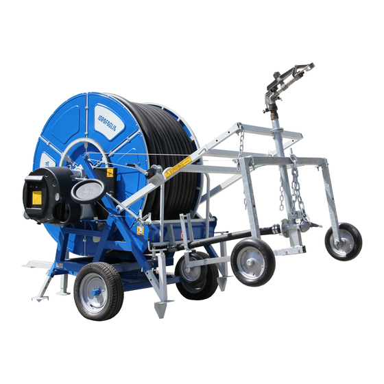
Machine Description TURBOCAR 1/21 DESCRIPTION OF THE MACHINE PAR. DESCRIPTION Operating principle 1. OPERATING PRINCIPLE Hose reel irrigators mainly consists of a long range irrigator, placed on a rubber wheel trolley connected to a polyethylene hose. 1 Winder roller or drum or reel 2 Superstructure or upper frame 3 Hose guide system 4 Long range irrigator... -
Page 21: Main Components
Machine Description TURBOCAR 2/21 DESCRIPTION OF THE MACHINE PAR. DESCRIPTION Main components 2. MAIN COMPONENTS The main components of the TURBOCAR are listed and described below 2.1 TURBINE Device consisting of an impeller that exploits water pressure to move the gearbox for roller rotation, so it reels in the PE hose. - Page 22 Machine Description TURBOCAR 3/21 2.3 SAFETY DEVICES FOR PTO AND REELING IN OUT OF STOWED POSITION Protection cap for the PTO and the mechanical stop system, in the event the hose should come out of the roller (bar joint). 2.4 MOTION DRIVE TO THE ROLLER VIA CROWN GEAR Transmission between gearbox and roller is direct via pinion keyed onto the output shaft of the gear block and the crown gear welded onto the side of the roller.
- Page 23 Machine Description TURBOCAR 4/21 2.6 BYPASS TO ADJUST SPEED Device placed near the turbine, on the water system which lets more or less water flow into the turbine, in order to adjust the PE hose reeling in speed. 2.7 GLYCERINE PRESSURE GAUGE Device placed near the turbine, which lets you read the water pressure on the machine.
- Page 24 Machine Description TURBOCAR 5/21 2.10 SUPERSTRUCTURE SLEWING The superstructure slewing turntable is normally blocked. Rotation takes place manually by removing the block. The block may be removed either through a release lever (first ensure you have removed the safety pin) or, in small-sized structures, by removing and replacing the pins blocking the turntable.
- Page 25 Machine Description TURBOCAR 6/21 2.13 3-WHEEL IRRIGATOR TRAVELLER 3-wheel irrigator trolley connected to the PE hose (standard model). 2.14 IRRIGATOR WITH SET OF NOZZLES Device fixed to the trolley that distributes the water evenly on the field. 2.15 POLYETHYLENE HOSE PE hose.
-
Page 26: Dimensions
Machine Description TURBOCAR 7/21 DESCRIPTION OF THE MACHINE PAR. DESCRIPTION Dimensions 3. DIMENSIONS Weights and overall dimensions... -
Page 27: Environmental Conditions
Machine Description TURBOCAR 8/21 DESCRIPTION OF THE MACHINE PAR. DESCRIPTION Environmental conditions 4. ENVIRONMENTAL CONDITIONS The machine does not require special environmental conditions and will be installed outdoors. The operations for placing the machine must always be performed assuring the stability of the irrigator during its operation. -
Page 28: Technical Specifications
Machine Description TURBOCAR 9/21 DESCRIPTION OF THE MACHINE PAR. DESCRIPTION Technical specifications 6. TECHNICAL SPECIFICATIONS... - Page 29 Machine Description TURBOCAR 10/21...
-
Page 30: Tools
Machine Description TURBOCAR 11/21 DESCRIPTION OF THE MACHINE PAR. DESCRIPTION Tools 7. TOOLS The machine is not supplied with any tools. Only if a control unit is installed, a manual lever is provided to be fitted in an emergency on the bypass valve, in the event problems should occur with the control unit/electric motor etc. -
Page 31: Standard Supply
Machine Description TURBOCAR 12/21 DESCRIPTION OF THE MACHINE PAR. DESCRIPTION Standard supply 9. STANDARD SUPPLY The Machine is supplied with complete outfitting for commissioning. Standard supply: turbine; gearbox with gears in oil bath; safety devices for PTO and reeling in out of stowed position; motion drive to the roller via crown gear;... -
Page 32: Accessories
Machine Description TURBOCAR 13/21 DESCRIPTION OF THE MACHINE PAR. DESCRIPTION Accessories 10. ACCESSORIES Below is a list of accessories that may be fitted on the various turbocar models: • FLEXIBLE HOSE WITH JOINTS: hose connecting the machine and the water supply line. •... - Page 33 Machine Description TURBOCAR 14/21 • INLET SOLENOID VALVE FOR SLOW CLOSING: device that closes water inlet into the machine at the end of irrigation. It behaves like the inlet water valve but closure takes place progressively in about 3 minutes. •...
- Page 34 Machine Description TURBOCAR 15/21 • SOLAR PANEL: device to keep the battery charged. • COMPRESSOR: device to partially empty the water inside the PE hose. • HYDRAULIC ACCESSORIES FOR MOVEMENT − distributor (with 1, 2 or 3 levers) with quick couplings to load the trolley, place the feet or superstructure slewing;...
- Page 35 Machine Description TURBOCAR 16/21 • LIGHT BAR ADAPTATION: adjustable, adjustable and tipping. • FRAME ON 4 ROCKER WHEELS: machine with 4 wheels instead of 2. • DOUBLE CROWN GEAR FOR REELING IN: roller drive with double crown gear. • TOOL BOX ON FRAME: tool box on the frame. •...
- Page 36 Machine Description TURBOCAR 17/21 • DIESEL ENGINE (PULL OR ELECTRIC START) REPLACING THE TURBINE FOR BELT OR HYDRAULIC REELING IN: motor used to reel in the PE hose (possibly also for hydraulic controls) to replace the turbine. • PETROL ENGINE WITH PULL START FOR HYDRAULIC CONTROLS: engine used for the hydraulic movements of the machine.
- Page 37 Machine Description TURBOCAR 18/21 • HOT-DIP GALVANISED FRAME OR ROLLER • ROAD APPROVAL • HP TROLLEY: trolley for high pressure adjustable up to 330 m. • OFFSET TROLLEY: trolley with hose in axis with the right wheel or with the left wheel of the trolley.
- Page 38 Machine Description TURBOCAR 19/21 • POSSIBLE TROLLEY ADAPTATIONS − swivel wheels; − cast iron wheels; − direction discs; − pneumatic oversized trolley nose wheel; − pneumatic wheels. • TROLLEY EXTENSION: device to lift the irrigator into the trolley. • QUICK IRRIGATOR RELEASE: device to quickly disconnect the irrigator from the trolley. •...
- Page 39 Machine Description TURBOCAR 20/21 • IRON OR CONCRETE BALLAST: iron or concrete weights to be applied to the trolley. • WATER BALLAST TANK: tank to be filled with water and applied to the trolley to act as ballast. • RIGID DRAWBAR ON THE TROLLEY: trolley towing drawbar in place of the standard chain. •...
- Page 40 Machine Description TURBOCAR 21/21 • OVERTREE KIT: kit to lift the irrigator. • OVERTREE KIT: slide with adjustable sprinklers. • SECOND IRRIGATOR KIT MOUNTED ON MACHINE FRAME: second small irrigator, actuated by manually opening a ball valve (if there is a control unit it can be controlled automatically, through an electric motor installed on the ball valve).
-
Page 41: Safety
Safety TURBOCAR 1/10 SAFETY PAR. DESCRIPTION General warnings 1. GENERAL SAFETY WARNINGS Before making the Machine operational, carefully read the instructions in this Manual and carefully follow the indications herein. The manufacturer has strived to ensure this Machine has been designed to make it INTRINSICALLY SAFE to the extent possible. - Page 42 Safety TURBOCAR 2/10 IMPORTANT! The manufacturer disclaims any liability for damage caused by the Machine to persons, animals or property in the event of: use of the Machine or intrusion in the area of operations by personnel not adequately trained; misuse of the machine;...
- Page 43 Safety TURBOCAR 3/10 Put the Machine out of order if any operation abnormalities occur and perform the appropriate checks or repairs. Ensure there are no objects between the Machine parts. After any maintenance operation, ensure no object remains between the moving parts. In order to assure the utmost safety when moving the Machine, however, it is FORBIDDEN: •...
-
Page 44: Intended Use
Safety TURBOCAR 4/10 SAFETY PAR. DESCRIPTION Intended use 2. INTENDED USE Machine operator: operator authorised to use the machine (strictly following the manufacturer’s instructions) in compliance with the laws in force in the machine user’s country. The machine has been solely designed and constructed for irrigation of agricultural plots with any kind of crop, parks, sport facilities and hothouses. -
Page 45: Contraindications For Use
Safety TURBOCAR 5/10 SAFETY PAR. DESCRIPTION Contraindications for use 3. CONTRAINDICATIONS FOR USE The turbocar must not be used: • for uses other than set out under 3.2, for other uses or not mentioned in this manual; • with circumvented safety devices or not working; •... -
Page 46: Safety Devices
Safety TURBOCAR 6/10 SAFETY PAR. DESCRIPTION Safety devices 5. SAFETY DEVICES The following safety devices are installed on the Machine: 1. protection devices for PTO; 2. guard between roller crown gear and gearbox pinion; 3. guard on roller/sliding bar transmission; 4. -
Page 47: Signs
Safety TURBOCAR 7/10 SAFETY PAR. DESCRIPTION Signs 6. SIGNS The following signs must be installed near the Machine and its operating area: List of Danger signs: Sign indicating hot surface hazard (if compressor is installed): Sign indicating upper limbs crushing hazard; Sign indicating entrainment or dragging hazard;... - Page 48 Safety TURBOCAR 8/10 List of Prohibition signs: Sign indicating prohibition for unauthorised persons to go near or stand near the machine; Sign indicating prohibition to remove safety devices; Sign indicating prohibition to perform maintenance operations with moving parts; Sign indicating prohibition to exceed the towing speed limit (if the Machine is approved, the limit specified on the registration paper/technical annex applies).
-
Page 49: Residual Risks
Safety TURBOCAR 9/10 SAFETY PAR. DESCRIPTION Residual risks 7. RESIDUAL RISKS DEFINITION OF RESIDUAL RISK: A residual risk is that remaining after all protection measures have been taken into account and implemented. It is required to pay attention to the following residual risks which exist when using the Machine and cannot be eliminated. - Page 50 Safety TURBOCAR 10/10 ATTENTION: HOT SURFACES The parts of the machine (compressor, if any) that may reach high temperature above 80° and that may be accessed by the operator or maintenance technician or, in the event of emergency, while performing their normal activity have been protected.
-
Page 51: Installation
Should any faults be found, the haulier firm must be alerted urgently for making the insurance claim, making the relevant note on the transport document. The shipping department of Idrofoglia S.r.l. should be informed at the same time. -
Page 52: Storage And Unpacking
Installation TURBOCAR 2/25 INSTALLATION PAR. DESCRIPTION Storage and unpacking 2. STORAGE AND UNPACKING As soon as it is received, the turbocar and all the material in the supply must be stored in adequate premises, preferably covered and dry, especially when it is not foreseen to be actually used for a long time. -
Page 53: Lifting, Handling And Unloading
Installation TURBOCAR 3/25 INSTALLATION PAR. DESCRIPTION Lifting, handling and unloading the turbocar in the operating place 3. LIFTING, HANDLING AND UNLOADING THE TURBOCAR IN THE OPERATING PLACE Driver of lifting and handling equipment: operator authorised to use lifting and handling equipment for materials and machines (strictly complying with the manufacturer’s instructions) in compliance with the laws in force in the machine user’s country. - Page 54 Installation TURBOCAR 4/25 INSTALLATION PAR. DESCRIPTION Transporting the turbocar in the place of operation. 4. TRANSPORTING THE TURBOCAR IN THE PLACE OF OPERATION While transporting the turbocar with tractor, IT IS REQUIRED TO STRICTLY COMPLY with the following procedure: While towing the turbocar to the place of operation: check the trolley tyres to ensure their pressure is adequate;...
- Page 55 Installation TURBOCAR 5/25 INSTALLATION PAR. DESCRIPTION Assembly instructions 5. ASSEMBLY INSTRUCTIONS Machine operator: operator authorised to use the machine (strictly following the manufacturer’s instructions) in compliance with the laws in force in the machine user’s country. A good and careful operator must adhere to essential and simple rules of conduct to assure their own safety, that of others and to preserve the self-propelled machine from any damage.
- Page 56 Installation TURBOCAR 6/25 ASSEMBLY OF WHEELS, DRAWBAR LIFTING FOOT AND BOOM FEET (WHERE ANY) IN THE MACHINE: In the case where the machine is delivered with lower base disassembled from the upper one, first place the lower base with turntable (the latter is already mounted by the manufacturer) on stands (fig.
- Page 57 Installation TURBOCAR 7/25 3) mount the boom feet (where present), adjust the required height and block them with pin and cotter (fig. 4.5.5 - 4.5.6); (fig. 4.5.5) (fig. 4.5.6) 4) mount the drawbar lifter foot, move the foot near foot support (G) (where present) and in larger machines fix it with the two pins and cotters (fig.
- Page 58 Installation TURBOCAR 8/25 If the machine is delivered with upper and lower base already assembled, it must be lifted either with forklift truck or crane (see paragraph 4.3) then perform assembly of the axle shafts, wheels, boom feet (where present) and the drawbar lifter foot as explained above (only if these components have been delivered disassembled).
-
Page 59: Assembly
Installation TURBOCAR 9/25 ASSEMBLY OF THE UPPER BASE AND TURNTABLE: In most cases the machine is delivered already assembled, that is with the lower base fastened to the upper one (in which case switch to item 5.4); if the machine is delivered disassembled, first of all follow items 5.1, 5.2 as explained above, to prepare the lower frame, then: 1) use a forklift truck or crane (see paragraph 4.3), lift the upper frame (I) and place it... - Page 60 Installation TURBOCAR 10/25 For the larger machines, in most cases, the spades must be prepared (M) inserted and fixed with screws and self-locking nut on the extension (N) (fig. 4.5.24 – 4.5.25). It is very important to know that spades are not all the same for all the machine models, that is why the protruding part of the spade must always be placed outwards (fig.
- Page 61 Installation TURBOCAR 11/25 If the machine is delivered with trolley loader and extensions disassembled: 1) use a forklift truck or crane (see paragraph 4.3) to lift the trolley loader (O) and fix it with screws and self-locking nuts on the two attachments (P) welded on the frame(fig.
- Page 62 Installation TURBOCAR 12/25 EXTRACTION OF ROTATION BLOCKING SAFETY PIN AND MACHINE ROTATION: The rotation blocking safety pin (R) is the blocking system of the upper base; it must always be installed during transport of the machine on roads; when the machine is used to irrigate, depending on the position of the upper base, in most cases it cannot be inserted.
- Page 63 Installation TURBOCAR 13/25 ASSEMBLY OF COMPONENTS/ACCESSORIES: It is now possible to assemble (if disassembled) any other components or accessories (if any) such as casing, water system (rarely - attention to assembling the seal), pump rod, handwheel, approval, solar panel, flashing light, hose reel, second irrigator kit, light bar, tool box etc.
- Page 64 Installation TURBOCAR 14/25 HOSE UNWINDING TO FIX TROLLEY: In this stage, the machine is prepared to be connected to the irrigator trolley, to do so: 1) tie a strap to the hose flange (fig. 4.5.39); 2) remove the ratchet (S) (roller crown blocking stop), possibly using the handwheel on PTO (fig.
- Page 65 Installation TURBOCAR 15/25 Trolley G1.1-G1 Trolley G1-G2 Trolley G3-G4 Trolley G4-G4S-G5 Trolley G5-G5S-G6 Trolley off axis Overtree trolley Underfoliage trolley Corn type trolley HP trolley 4 swivel wheels Cast iron wheels...
- Page 66 Installation TURBOCAR 16/25 Direction discs Extension for irrigator Concrete ballasts Iron ballasts Ballast water tank Rigid drawbar Small irrigator Width adjustable legs Quick release Height adjustable legs Supplementary valve Pneumatic wheel...
- Page 67 Installation TURBOCAR 17/25 5.11 TROLLEY HOSE FIXING: In this stage the hose is connected to the flange of the irrigator trolley. To do so: 1) loosen the stop (V) in the trolley slide fork (fig. 4.5.45); 2) insert the PE hose and tighten again the stop (V) in the trolley slide fork (fig. 4.5.46);...
- Page 68 Installation TURBOCAR 18/25 5.12 HOSE WINDING, TROLLEY LOADER LOWERING, TROLLEY LOADER ADJUSTMENT, TROLLEY HITCHING, LIMIT STOP BRACKET ADJUSTMENT AND FIXING, TROLLEY LOADER LIFTING AND ROTATION/BLOCKING OF THE MACHINE: In these stages the trolley is mounted on the machine, in order to be ready for the irrigation stage: 1) Hose winding: 1) insert the ratchet (S) (roller crown blocking stop), possibly using the handwheel...
- Page 69 Installation TURBOCAR 19/25 • For smaller machines where the trolley loader (O) is independent from the spades (therefore there are no vertical extensions), one must use the lever of the mechanical winch (CA), and turn it anti-clockwise. (fig. 4.5.57); (fig. 4.5.57) •...
- Page 70 Installation TURBOCAR 20/25 5) Adjustment and fixing of the limit stop bracket: 1) push the bar joint (U) with one hand to stroke end, and block it with the vertical rotation of the limit stop bracket (T) (fig. 4.5.63); 2) block the screws (GA) of the limit stop bracket (fig. 4.5.64); (fig.
- Page 71 Installation TURBOCAR 21/25 • For smaller machines where the trolley loader (O) is independent from the spades (therefore there are no vertical extensions), one must use the lever of the mechanical winch (CA), and turn it clockwise. (fig. 4.5.69 - 4.5.70); (fig.
- Page 72 Installation TURBOCAR 22/25 INSTALLATION PAR. DESCRIPTION Connection of the starter batteries 6. CONNECTION OF THE STARTER BATTERIES Machine operator: operator authorised to use the machine (strictly following the manufacturer’s instructions) in compliance with the laws in force in the machine user’s country. The turbocar is supplied with 12 V starter battery with variable capacity, if there is an automatic control unit installed on the machine.
- Page 73 Installation TURBOCAR 23/25 INSTALLATION PAR. DESCRIPTION Topping up and charging the battery 7. TOPPING UP AND CHARGING THE BATTERY Machine operator: operator authorised to use the machine (strictly following the manufacturer’s instructions) in compliance with the laws in force in the machine user’s country.
-
Page 74: Commissioning
Installation TURBOCAR 24/25 For topping up, the battery must be filled with sulphuric acid at the density required by the manufacturer (usually 1.27 Kg/l) up to the indicated level (about 10-15 mm above the plates, temperature above 15°C). Wait at least 30 minutes before installation on board. During cold periods or if storage exceeds 6 months, before charging the battery, let it “stand”... - Page 75 Installation TURBOCAR 25/25 One should also: constantly check whether there are any loosened fixings; check the source of any abnormal noise or vibrations, which if neglected might lead to faults or abnormalities; immediately report oil leaks or acid leaks from the batteries; do not perform repairs unless expressly authorised and specifically rained for the purpose.
-
Page 76: Use Of The Machine
Use of the TURBOCAR 1/24 Machine USE OF THE MACHINE PAR. DESCRIPTION Checks before starting up the turbocar 1. CHECKS TO BE PERFORMED AND PREPARATION BEFORE STARTING UP THE TURBOCAR Machine operator: operator authorised to use the machine (strictly following the manufacturer’s instructions) in compliance with the laws in force in the machine user’s country. - Page 77 Use of the TURBOCAR 2/24 Machine During preparation of the turbocar, the following points must be adhered to: 1) move the machine to the place where it is to be parked for irrigation; when choosing the placement it is required to ensure that: the ground on which the turbocar is placed is sufficiently firm;...
- Page 78 Use of the TURBOCAR 3/24 Machine c) where present, lower the boom feet (C), by removing then placing back the pin and cotter, so that they are as close as possible to the ground (fig. 5.1.6), then lower the machine, by rotating anti-clockwise the drawbar lifter foot crank (A) (fig. 5.1.7) or if the machine is hydraulic, by means of the distributor lever (B) (fig.
- Page 79 Use of the TURBOCAR 4/24 Machine c) place the rotation blocking safety pin back, if possible (fig. 5.1.11); in smaller machines, where there is no rotation lever, it is MANDATORY to place the two safety pins back, in any position (fig. 5.1.12); (fig.
- Page 80 Use of the TURBOCAR 5/24 Machine In both cases, with the operation to anchor the spades into the ground, the trolley loader is also lowered, and consequently the trolley is released from the trolley loader (fig. 5.1.14); (fig. 5.1.14) in smaller machines spade lowering is independent from the trolley loader; therefore it is required to: 1) lower the extension (G) by removing then placing back the pin and cotter, so that they are as close as possible to the ground (fig.
-
Page 81: Starting Up
Use of the TURBOCAR 6/24 Machine USE OF THE MACHINE PAR. DESCRIPTION Starting up 2. STARTING UP Machine operator: operator authorised to use the machine (strictly following the manufacturer’s instructions) in compliance with the laws in force in the machine user’s country. Mechanical maintenance technician: skilled technician, able to operate the machine in normal conditions, to act on mechanical parts to perform the required adjustments, maintenance and repairs. - Page 82 Use of the TURBOCAR 7/24 Machine - PAYING OUT: proceed as follows to pay out the hose: 1) connect one end of the flexible hose to the water inlet of the machine (fig. 5.2.1) while leaving the other end free (fig. 5.2.2), possibly in a ditch next to the machine, so that the water is able to come out for easier hose paying out (lighter), and to prevent any air bubbles from forming inside the PE hose;...
- Page 83 Use of the TURBOCAR 8/24 Machine (fig. 5.2.5) (fig. 5.2.6) (fig. 5.2.7) (fig. 5.2.8) (fig. 5.2.9) (fig. 5.2.10) 3) the gear knob (this does not apply for machines with single speed gearbox) may be in any position (fig. 5.2.11); (fig. 5.2.11) 4) ensure the bypass is open (see paragraph 5.3.1);...
- Page 84 Use of the TURBOCAR 9/24 Machine 6) disconnect the blocking stop (A) crown gear roller (ratchet) (fig. 5.2.14); (fig. 5.2.14) THE HANDWHEEL MUST NEVER BE LEFT ENGAGED IN THE GEARBOX PTO 7) place the tractor near the irrigator trolley in order to hitch it to the tractor, through the chain or rigid drawbar (optional);...
- Page 85 Use of the TURBOCAR 10/24 Machine (fig. 5.2.16) (fig. 5.2.17) (fig. 5.2.18) 9) disconnect the trolley from the tractor; 10) ensure the angle of the irrigator range is as desired. Should you wish to change this angle, act on the appropriate inversion stops without any water; ENSURE THE WATER JET DOES NOT HIT POWER LINES, HIGH VOLTAGE CABLES, HOUSES, ROADS OR WORKPLACES ETC.
- Page 86 Use of the TURBOCAR 11/24 Machine 3) place the gear release lever on “1” START. In most machines the gear is engaged by applying force on the black knob of the lever and pushing right (fig. 5.2.22); it is very important to ensure the position of the lever on the gearbox is “1”...
- Page 87 Use of the TURBOCAR 12/24 Machine (fig. 5.2.28) 6) connect the other end of the flexible hose to the water line (fig. 5.2.29), paying attention so that all fitting hooks are properly inserted (if the machine has double inlet, ensure the second inlet is closed with the cap supplied);...
- Page 88 Use of the TURBOCAR 13/24 Machine In many machines, automatic control units are installed to have constant hose reeling in speed; basically, all control units are powered by a battery, and through a sensor they control an electric motor fitted on the bypass valve, which adjusts the PE hose reeling in speed. Based on the type of control unit, there will be a varying umber of functions, also depending on the optional features (flashing light, second irrigator, water valve, pressure switch, GSM etc.) fitted on BEFORE STARTING THE CONTROL UNIT CAREFULLY READ THE USER AND...
- Page 89 Use of the TURBOCAR 14/24 Machine AT THE END OF IRRIGATION THE LIMIT STOP BRACKET DOES NOT RELEASE THE GEARBOX, THEREFORE, WHEN THE IRRIGATOR TROLLEY IS NEAR THE IRRIGATING MACHINE, GRADUALLY REDUCE PTO ROTATING SPEED IN THE LAST FEW METRES, UNTIL COMPLETELY STOPPED.
-
Page 90: Adjustment Instructions
Use of the TURBOCAR 15/24 Machine USE OF THE MACHINE PAR. DESCRIPTION Adjustment instructions 3. ADJUSTMENT INSTRUCTIONS Machine operator: operator authorised to use the machine (strictly following the manufacturer’s instructions) in compliance with the laws in force in the machine user’s country. Mechanical maintenance technician: skilled technician, able to operate the machine in normal conditions, to act on mechanical parts to perform the required adjustments, maintenance and repairs. - Page 91 Use of the TURBOCAR 16/24 Machine (fig. 5.3.1) (fig. 5.3.2) 2) BYPASS VALVE ADJUSTMENT: The bypass lever connects the bar joint to the bypass valve; this bypass valve is a speed compensator, which allows the PE hose reeling in speed to be kept as constant as possible. If hose reeling in is very variable (take into account that a speed average should always be made between the first and last layer of PE hose on the roller), the bypass lever connection must be moved on the bar joint (fig.
- Page 92 Use of the TURBOCAR 17/24 Machine In the latter case (machine during irrigation, with pressurised hose and reeling in) it is required to: a) NEVER DISCONNECT THE GEAR LEVER (IT MUST BE PLACED ON “1” START - see paragraph 5.2.2 - IRRIGATION item 3) b) open the bypass valve almost completely, so that the turbine impeller speed is almost zero (see paragraph 5.3.1);...
-
Page 93: Turning Off
Use of the TURBOCAR 18/24 Machine USE OF THE MACHINE PAR. DESCRIPTION Turning off 4. TURNING OFF Machine operator: operator authorised to use the machine (strictly following the manufacturer’s instructions) in compliance with the laws in force in the machine user’s country. Mechanical maintenance technician: skilled technician, able to operate the machine in normal conditions, to act on mechanical parts to perform the required adjustments, maintenance and repairs. - Page 94 Use of the TURBOCAR 19/24 Machine (fig. 5.4.1) (fig. 5.4.2) WATER VALVE START END OF IRRIGATION INLET OPEN CLOSES DRAIN CLOSES OPEN 3) Lift the spades of the machine from the ground: if the manual pump (A) is fitted on, the lever must be inserted in the appropriate hole, turn the knob (B) anti-clockwise and pump until their stroke end and the trolley is lifted off the ground (fig.
- Page 95 Use of the TURBOCAR 20/24 Machine in smaller machines spade lifting is independent from the trolley loader; therefore it is required to: 1) rotate the crank anti-clockwise to lift the foot (D) to stroke end (fig. 5.4.6); 2) lift the extension (E) to stroke end, by removing then placing back the pin and cotter, (fig.
- Page 96 Use of the TURBOCAR 21/24 Machine c) place the rotation blocking safety pin back (fig. 5.4.12); in smaller machines, where there is no rotation lever, place the two safety pins back (fig. 5.4.13); (fig. 5.4.12) (fig. 5.4.13) 6) lift the central parking foot and hitch the machine to the tractor, then lift the boom feet (where present);...
- Page 97 Use of the TURBOCAR 22/24 Machine c) where present, lift the boom feet (M) by removing then placing back the pin and cotter, so that they are as far as possible from the ground (fig. 5.4.18); (fig. 5.4.18) d) if present, connect the lights bar and braking systems to the tractor; If the compressor is fitted on the machine (optional) and you wish to partially empty the PE hose from water, this operation must be performed before hitching the machine to the tractor;...
- Page 98 Use of the TURBOCAR 23/24 Machine • THE DRAIN CAP OF THE IRRIGATOR TROLLEY HAS BEEN REMOVED (fig. 5.4.21); (fig. 5.4.21) • THE COMPRESSOR’S SYSTEM HAS BEEN PROPERLY CONNECTED TO THE MACHINE’S SYSTEM, ENSURING ALL HOOKS OF THE FITTING ARE PROPERLY INSERTED (fig.
- Page 99 Use of the TURBOCAR 24/24 Machine • ONCE THE COMPRESSOR IS AT OPERATING SPEED (540 RPM), ENSURE ONE DROP OF OIL PER SECOND COMES DOWN IN THE OIL REGULATOR(S) FITTED ON IT (THIS SYSTEM LUBRICATES THE BLADES INSIDE THE COMPRESSOR); TO ADJUST USE THE KNOB (S) (fig.
-
Page 100: Maintenance
Maintenance TURBOCAR MAINTENANCE PAR. DESCRIPTION General warnings 1. GENERAL WARNINGS Machine operator: operator authorised to use the machine (strictly following the manufacturer’s instructions) in compliance with the laws in force in the machine user’s country. Mechanical maintenance technician: skilled technician, able to operate the machine in normal conditions, to act on mechanical parts to perform the required adjustments, maintenance and repairs. -
Page 101: Maintenance
Maintenance TURBOCAR MAINTENANCE PAR. DESCRIPTION Maintenance 2. MAINTENANCE Machine operator: operator authorised to use the machine (strictly following the manufacturer’s instructions), in compliance with the laws in force in the machine user’s country. Mechanical maintenance technician: skilled technician, able to operate the machine in normal conditions, to act on mechanical parts to perform the required adjustments, maintenance and repairs. - Page 102 Maintenance TURBOCAR (tab. 6.2.1) TO BE CARRIED OUT AT THE END EVERY 3 EVERY 20 AND START POS. DESCRIPTION IRRIGATION IRRIGATION OF THE IRRIGATING SEASON CHECK GEARBOX OIL LEVEL (SAE90) GREASE THE TURNTABLE GREASE DRAWBAR LIFTING FOOT (IF MECHANICAL-MANUAL) GREASE SEAL (WATER INLET ON ROLLER) GREASE ROLLER SWIVEL SUPPORTS GREASE SLIDING BAR CHAIN GREASE ROLLER CROWN GEAR AND...
- Page 103 Maintenance TURBOCAR (fig. 6.2.1)
-
Page 104: Spare Parts And Accessories
ALWAYS USE ORIGINAL SPARE PARTS. Note. Idrofoglia S.r.l. shall not be liable for breakdowns, malfunctions or damage to persons or property arising from use of non original parts. Using non original spare parts is recommended against, and should this happen, Warranty conditions shall be forfeited (if still in force) as well as the Manufacturer’s Liability in using the Machine/System and... -
Page 105: Waste Disposal
Supplementary TURBOCAR Instructions SUPPLEMENTARY INSTRUCTIONS PAR. DESCRIPTION Waste disposal 1. WASTE DISPOSAL The user is responsible for ensuring waste is properly disposed of according to the laws in force in their country. Disposal of replaced parts must be carried out in compliance with the regulations in force in the country where the Machine is used. -
Page 106: Safe Work Procedures
Supplementary TURBOCAR Instructions Any disposal of these or other components or ancillary fluids (starter battery, ancillary cleaning material such as oily rags etc.) must be carried out according to the regulations in force at the time of demolition. For proper disposal, use specialised services authorised to collection and processing or contact the competent authorities for places and methods.
Need help?
Do you have a question about the TURBOCAR G1.1 and is the answer not in the manual?
Questions and answers