Advertisement
Quick Links
U S E R F R I E N D LY O P T I O N
...an alternate universe
of airflow performance.
See INSIDE for more!
Read this manual Before
installing your UFO Aeration.
It contains important stuff that
you need to know so that you
don't hurt yourself or others.
Installation
the future of
mANUAL
grain
aeration
Advertisement

Related Manuals for S3 UFO AERATION

Summary of Contents for S3 UFO AERATION
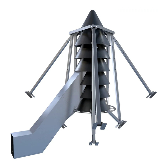
- Page 1 U S E R F R I E N D LY O P T I O N ...an alternate universe of airflow performance. See INSIDE for more! Read this manual Before installing your UFO Aeration. It contains important stuff that you need to know so that you don’t hurt yourself or others.
- Page 2 LET’S GET STARTED… Thank you for your purchase of UFO Aeration. UFO Aeration is recommended for hopper bottom bins that are less than 30’ in diameter and have a wall height of less than 30’. It is for use in grain only. Do not use it with fertilizer. Do not use it with a heater.
- Page 3 SAFETY UFO Aeration is easy to install but does require that you know how to safely operate tools like a torch or cutting wheel. There are a few things to watch out for: 1. Wear appropriate personal protective equipment such as safety glasses, steel toed boots, and safety gloves.
- Page 4 THE PARTS IN YOUR KIT 1 – Base Ring, made up of 3 identical parts that will form a full ring that is 36” in diameter 1 – Upper Ring, made up of 3 identical bent parts that will form a full ring that looks almost like a triangle with a central hole in it.
-
Page 5: Installation
INSTALLATION You are going to need a few tools: 1. Electric drill with 7/16” bit and a ½” bit 2. Ox-fuel cutting torch or hand grinder with part off wheel 3. Marker 4. Level 5. 9/16” and 3/4” open ended wrench 6. - Page 6 We have broken the installation into 8 big steps: 1. Assemble the Lower Support Base Sub Assembly 2. Mount the Lower Support Base Sub Assembly and add the Gray Inboard Legs 3. Mount the 1 Stage and the Column Legs to the Lower Support Base Sub Assembly 4.
- Page 7 Figure 2: Base Ring Assembly With the Connecting Brackets facing upward (yes, the Base Ring is upside down but, trust us, it’s easier), bolt the unslotted end of the Short Legs to the Connecting Brackets, using one 1/2” bolt, two 1/2” washers, and one 1/2” nut per Connecting Bracket.
- Page 8 Figure 3: Lower Support Base Sub Assembly Bolt a Mounting Foot to the slotted end of each of the Short Legs, using one 3-1/2” x 1/2” bolt, two 1/2” washers, and one 1/2” nut per Mounting Foot, as per Figure 3. Thread the nuts on finger tight –...
- Page 9 Consider where you want to position the ducting that connects your aeration fan to your UFO Aeration. Rotate the Lower Support Base Sub Assembly into a position that aligns one of the V-notches, as shown in Figure 4, in the Base Ring with where the ducting will go.
- Page 10 Bolt the bottom Mounting Feet to the hopper using four 3/8” bolts and nuts per Mounting Foot, as per Figure 5. The nuts will be on the outside of the bin. Figure 5: Lower Support Base Sub Assembly Mounting ...
- Page 11 Insert the Base Disc so that it is nested into the hole in the Base Ring. Position it so that one side of the gap on the Base Disc is slightly offset from a seam on the base ring, and the other is slightly offset from the notch on the opposite side where the ducting will be installed.
- Page 12 Figure 7: Long Gray Inboard Leg Installation Figure 8: Close up of Legs Page 11 of 31...
- Page 13 3. MOUNT THE 1 STAGE AND THE LOWER COLUMN GRAY LEGS TO THE LOWER SUPPORT BASE SUB ASSEMBLY You are going to need: 1 – Stage, made up of 2 Halves From the Bolt Kit: 6 – self-tapping ¼” screws 12 –...
- Page 14 V-notch you are using to align your ducting. Rotate the 1 UFO Stage so that the angled tab on this leg is touching the “S3” logo on the stage. Ensure that the stage is still properly nested into the Base Disc, and the Base Disc into the Base Ring.
- Page 15 Figure 11: Installing the 1 Stage and Lower Column Gray Legs Place one Lower Column Leg, plate down, on top of the Base Ring, with the bent side of the plate pushed tight up against the 1st Stage as per Figure 11. Align the slots with a set of open holes on the Base Ring.
- Page 16 4. ASSEMBLE AND MOUNT THE REMAINING UFO STAGES You are going to need: Stages, made up of 2 Halves: UFO 4 Stage Kit = 6 more Halves UFO 6 Stage Kit = 10 more Halves From the Bolt Kit: 6 self-tapping ¼” screws 6 per UFO Stage –...
- Page 17 Figure 12: Interlocking the Stages Repeat. And repeat. And repeat until all Stages are on the unit as shown in Figure (6 Stage unit depicted). Figure 13: All Stages Installed Page 16 of 31...
- Page 18 5. ASSEMBLE THE INBOARD LEGS You are going to need: 3 – Upper Column (36” Black) Legs 3 – 44” Inboard Black Legs (with a notch cutout on one end) From the Bolt Kit: 3 – 3” x ½” bolts 3 –...
- Page 19 Figure 14: Installing the 36” Upper Column Black Leg Take a 44” Inboard Black Leg and slide it over the 46-1/2” Inboard Gray Leg which is in line with the leg assembled in the previous step. Pivot the gray and black legs up and attach the Inboard black leg at the top hole to the bracket at the top of the 36”...
- Page 20 Figure 15: Installing the Inboard 44” Black Leg 6. INSTALL THE UPPER RING You are going to need: The Upper Ring parts – 3 bent versions of the Base Ring parts From the Bolt Kit: 6 – 3/8” whiz nuts Page 19 of 31...
- Page 21 Figure 16: Installing the Upper Ring Install the Upper Ring parts one at a time. The bolts that stick out of the top leg bracket should align with the holes on the Upper Ring plates. Install 3/8” whiz nuts on the outside pairs of bolts (leave the inside bolts for now).
- Page 22 Ensure that none of the UFO Stages have rotated out of position by performing one last counter clockwise rotation of each of the stages from bottom to top. Place the Nose Cone on top of the top Stage and rotate it until it falls in. The lower circle of the Nose Cone should also be inset into the hole in the Upper Ring.
- Page 23 Figure 17: Installing the Nose Cone and Clamping Tabs Page 22 of 31...
- Page 24 Reaching into the bottom of the top Stage, fasten a screw through the top of that Stage in through the bottom of the Nose Cone to lock them together. Repeat this on the opposite side. See Figure 18. Figure 18: Fasten the Top Stage to the Nose Cone Page 23 of 31...
- Page 25 8. INSTALL THE OUTBOARD LEGS Refer to Figure 19. Find your remaining 3 Outboard Gray Legs, which have no washers welded to them. Carefully remove one ½” nut and washer from one of the brackets at the Upper Ring.
- Page 26 Figure 19: Installing the Outboard Black Legs 9. INSTALL THE DUCTING You are going to need: 1 – Upper Duct (it looks like a weird, notched claw) 1 – Lower Duct 1 – Duct Elbow, with End Cap (leave this outside of the bin) 1 –...
- Page 27 Figure 20: When you open up your UFO kit, the Lower Duct should already be inserted into the Upper Duct. If it isn’t or if you decided to take them apart, make sure that when you engage the Lower Duct into the Upper Duct the riveted seams are on opposite corners (as per Figure 21) to avoid unnecessary binding when sliding the two ducts within each other.
- Page 28 Figure 21: Duct Seams LOWER Ducting Rivet Seam UPPER Ducting Rivet Seam Slide the two notches of the ducting into the bottom rims of the 2 and 3 Stage, central to the V-notch in the Base Ring. Extend the Lower Duct out from the Upper Duct until it contacts the hopper cone. ...
- Page 29 Reinstall the Lower and Upper Ducting into the bottom rims of the 2 and 3 Stage, central to the V-notch on the Base Ring just like you did earlier. Using self-tapping screws, fasten the notched ducting to the UFO stage wall, per Figure 22.
- Page 30 Figure 23: Fastening the Ducts to Each Other Using the Duct Elbow as a guide, now assemble the Duct Flange to fit the Elbow properly, per Figure 24. Figure 24: Assembling the Mounting Flange From outside the bin, hold the Flange up to the duct opening that has been cut in the hopper and mark out the 12 mounting holes for the Flange.
-
Page 31: Contact Information
CONTACT INFORMATION: If you have any questions or need any help with your product call us at 306-773-0646 or toll free at 844-441-2020. The team at S3 is great and wants you to be happy with your purchase. Videos and other information can be found on our website at www.s3airsystems.com... - Page 32 Innovation Precision Sustainability • • DELTA HARROWS WIREFORM MANUFACTURING AIR SYSTEMS S3 Group Ltd. S3 Delta Harrows S3 Wireform S3 Air Systems S3 Manufacturing 2180 Oman Drive 800 S. Fremont Street 2180 Oman Drive 2180 Oman Drive 2180 Oman Drive P.O.
Need help?
Do you have a question about the UFO AERATION and is the answer not in the manual?
Questions and answers