Sign In
Upload
Download
Table of Contents
Contents
Add to my manuals
Delete from my manuals
Share
URL of this page:
HTML Link:
Bookmark this page
Add
Manual will be automatically added to "My Manuals"
Print this page
×
Bookmark added
×
Added to my manuals
Manuals
Brands
UTILEV Manuals
Forklifts
UT13PTE
Service manual
UTILEV UT13PTE Service Manual
1.3 –2.0t 3-wheel battery counte 2.0t 3-wheel battery counterbalanced forklift t rbalanced forklift truck
Hide thumbs
1
2
3
Table Of Contents
4
5
6
7
8
9
10
11
12
13
14
15
16
17
18
19
20
21
22
23
24
25
26
27
28
29
page
of
29
Go
/
29
Contents
Table of Contents
Bookmarks
Table of Contents
Table of Contents
Drive Drive System System
Gearbox
Pressure Adjustment of Main Pressure Adjustment of Main Safety Valve Safety Valve
Steering Steering System System
Steering Device
Steering Axle
Braking Braking System System
Brake Master Cylinder
Hand Brake
Hydraulic Hydraulic System System
Main Oil Pump
Multi-Way Valve
Hydraulic Schematic Diagram
Lifting Lifting System System
Mast
Lift Cylinder
Tilt Cylinder
Electrical Electrical System System
Controller
Circuit Diagram
Advertisement
Quick Links
1
Table of Contents
2
Gearbox
3
Drive Drive System System
4
Braking Braking System System
5
Controller
6
Electrical Electrical System System
7
Circuit Diagram
Download this manual
1.3
1.3
– –
Part No. 76002086
Part No. 76002086
2.0t 3-Wheel Battery Counterbalanced Forklift T
2.0t 3-Wheel Battery Counte
Service Manual
Service Manual
https://www.forkliftpdfmanuals.com/
rbalanced Forklift Truck
ruck
Table of
Contents
Previous
Page
Next
Page
1
2
3
4
5
Advertisement
Table of Contents
Need help?
Do you have a question about the UT13PTE and is the answer not in the manual?
Ask a question
Questions and answers
Related Manuals for UTILEV UT13PTE
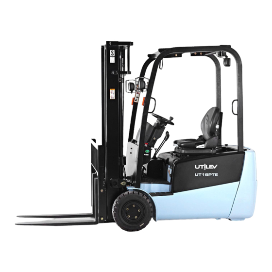
Forklifts UTILEV UT16PTE Service Manual
1.3 –2.0t 3-wheel battery counte 2.0t 3-wheel battery counterbalanced forklift t rbalanced forklift truck (29 pages)
Forklifts UTILEV UT20PTE Service Manual
1.3 –2.0t 3-wheel battery counte 2.0t 3-wheel battery counterbalanced forklift t rbalanced forklift truck (29 pages)
Forklifts UTILEV UT25P Operation And Maintenance Manual
2t-3.5t internal combustion counterbalanced forklift truck (149 pages)
Forklifts UTILEV UT25C Operation And Maintenance Manual
2t-3.5t internal combustion counterbalanced forklift truck (149 pages)
Forklifts UTILEV UT30P Operation And Maintenance Manual
2t-3.5t internal combustion counterbalanced forklift truck (149 pages)
This manual is also suitable for:
Ut15pte
Ut16pte
Ut18pte
Ut20pte
Table of Contents
Print
Rename the bookmark
Delete bookmark?
Delete from my manuals?
Login
Sign In
OR
Sign in with Facebook
Sign in with Google
Upload manual
Upload from disk
Upload from URL


Need help?
Do you have a question about the UT13PTE and is the answer not in the manual?
Questions and answers