Table of Contents
Advertisement
Quick Links
Advertisement
Table of Contents

Related Manuals for Sanmenxia ZM600


Summary of Contents for Sanmenxia ZM600
- Page 1 OPERATION MANUAL FOR GAUGE UNIT ZM600 Sanmenxia ZhongyuanJingmiCo.,Ltd...
- Page 2 In order to use the instrument safely, please follow the following instructions DANGER ⚫ Hazardous voltage can cause injury or death. ⚫ Do NOT take out the covers unless there is qualified maintenance personnel. ⚫ Please turn off the power switch and disconnect the power supply cable before taking outcovers.
-
Page 3: Table Of Contents
CONTENTS 1、Introduction ---------------------------------------------------------------1 2、Features---------------------------------------------------------------------2 3、Extension Function-------------------------------------------------------3 4、Interface --------------------------------------------------------------------3 4.1、Measuring Interface --------------------------------------------------4 4.2、Setting Interface -------------------------------------------------------6 4.3、Adjustment Interface--------------------------------------------------7 5、I/O Interface And Connection-------------------------------------------8 6、Method Of Use--------------------------------------------------------------11... -
Page 4: 1、Introduction
1、Introduction Z600 controller is based on the latest digital signal processing system, using the latest control technology designed for grinding machine processing on-line monitoring and control of the instrument. This controller will be processed or after the size of the workpiece, with electric sensor for measurement, if the use of air momentum meter for measurement, it needs to be measured through the pneumatic probe and AE converter. -
Page 5: 2、Features
2、Features 1) Intelligent control:All kinds of calculation and correction can be carried out within the standard range, or the machining size correction can be completed automatically under the control of the machine tool. In the process or after the processing of the measurement process, display a variety of measurement results and judge the status of the point, while sending a signal to control the movement of the machine. -
Page 6: 3、Extension Function
5)Optimized design, the whole machine can meet the industrial interference test. 3、 Extension Functions: 1)External compensation:The measured data are compensated and zeroed according to external input signals. Memory selection: In order to measure the discontinuous surface can set memory function, such as maximum memory. 3)BCD/ Binary: The digital interface to the machine tool. -
Page 7: Measuring Interface
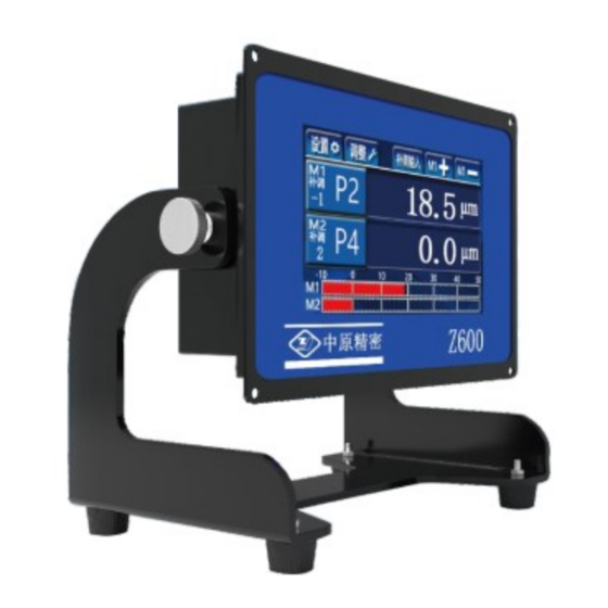
4.1 Measuring the interface Measurement interface Window functions:The measured value of the measuring item is displayed, adjusted and displayed in digital form. Instruction: Displays the measured value of the measured item. Display signal points. Displays the adjustment value of the corresponding measurement item of the channel.(Adjustment range:±60μm)... - Page 8 When there is a deviation between the actual size value and the expected measurement value, you can click the input deviation value to correct.You can also click to correct it。 Such as:The measured workpiece size is φ50.0(+0.02),The theoretical value of standard parts isφ50.01,Because of manufacturing deviation,The actual size of standard parts isφ50.009,When the null position of M1 is set with this standard component, the deviation between the actual value and the theoretical value is -1μm, it is necessary to conduct supplementary...
-
Page 9: Setting Interface
4.2 Setting interface If you need to change the setting parameters, click the number section, and the keyboard pops up for setting. Instruction: P1 Signal points of rough grinding ; P2 Signal points of fine grinding; P3 Light grinding signal points; P4 The signal point of retreating knife;... -
Page 10: 4.3 Adjustment Interface
M Measurement expression:Can choose G1 ,G2 ,G1+G2 ,G1-G2; S Filter way:Can choose 0, 1,2,3,4,5. (This option is a special function and is only available when the user makes a special order.) :M1/M2 setting interface toggle. 4.3 Adjustment interface Instruction: Display value: the value of the probe after processing; Reset value: the compensation value of the probe by the system after resetting;... -
Page 11: 5、I/O Interface And Connection
5. I/O interface and connection 37P communication socket Color A single Two terms One terms of Two terms of serial measureme measurement measurement number nt items measurement M1P1 M1P1 Pink M1P2 M1P2 Pink M1P3 M1P3 Pink M1P4 M1P4 Pink M2P1(+NG) M2P1 Pink M2P2(+OK) - Page 12 BCD2*10 M1/M2BCD2* Yellow BCD4*10 M1/M2BCD4* Yellow BCD8*10 M1/M2BCD8* Yellow BCD1*100 M1/M2BCD1* Yellow BCD2*100 M1/M2BCD2* Yellow Yellow BCD4*100 M1/M2BCD4* Yellow confirm BCD8*100 M1/M2BCD8* Green actuatin Output is Output is Green negative negative Green Green Green 485A Green 485B Green Green - 9 -...
- Page 13 According Display/out Green to switch put switch Adjust+ Green Adjust Gray Gray Determine Gray start Determine Gray start Gray COMIN Gray Gray The I/O parameters: Power:24V DC±20%(>10W) 24V and 0V are respectively connected to the output line yellow line 9 and gray line 7 Grounding: connect the ground wire of the machine tool to the screw of the grounding terminal on the right side of the switch Output signal: optical relay 200mA 24VAC/DC...
-
Page 14: 6、Method Of Use
6. Method Of Use 6.1Adjustment method for standard double rod single chann el sensor(ZHD-1070BC\1090BC\1080BC) Enter the boot screen and press the button above the screen set the display value after compensation to 0. Adjust the upper and lower contacts away from the measuring surface.Click ,the system enters the adjustment window, the interface displays G1, records the size of the display value, adjusts the... - Page 15 Enter the boot screen and press the button below the screen set the display value after compensation to 0. Adjust the contact away from the measuring surface.Click ,the system enters the adjustment window, the interface displays G1, records the display value, adjusts the contact to make the display value change to about 0 (the value is within ±30), and locks the contact.
- Page 16 6.4Adjustment method for standard pneumatic sensors(ZHS- AH series) Enter the boot screen and press the button below the screen set the display value after compensation to 0. Click ,the system enters the adjustment window, the interface displays G1, records the size of the display value, adjusts the throttle valve of the sensor, makes the display value change to about 0 (the value is within ±...
- Page 17 V1.1 20210930 Sanmenxia ZhongyuanJingmiCo.,Ltd Address: east section of weiliu road, sanmenxia industrial park, henan, China Tel:0398-2751818 Fax:0398-2751819 Postcode:472000 http://www.zyjm.com...
Need help?
Do you have a question about the ZM600 and is the answer not in the manual?
Questions and answers