Advertisement
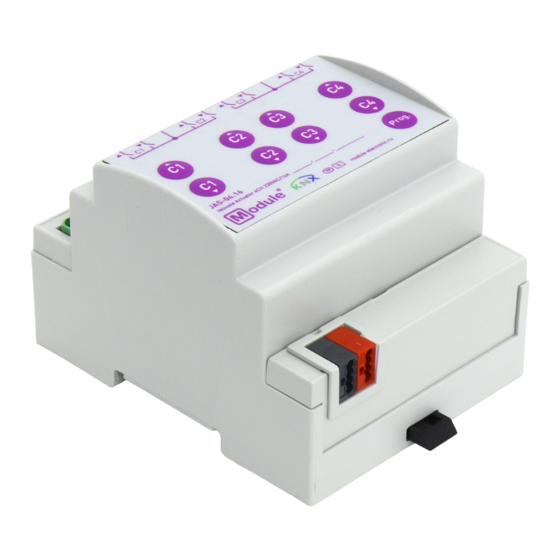
JALOUSIE ACTUATOR
JAS-04.16
BASIC INFORMATION
The jalousie actuator is designed to control motorized curtains, jalousie, roller shutters and similar devices
powered by AC. Each output has a bistable relay, designed for high inrush currents, and can be controlled
manually.
• 4 independent channels for a maximum capacitive load of
•
Ability to connect outputs to different phases
• Manual control of outputs using front panel buttons
• LED indication of output status
• Extendet logic and scenario functions for each output
• The choice of operation mode curtains / jalousie
• Saving settings during a KNX power failure
• Power supply via KNX bus
• DIN rail 35 mm mounting
1. Outputs
2. Output status indicator LED
4. Programming button
module-electronic.ru, info@module-electronic.ru
phone: +7-495-150-27-25
page 1
140µF
1
5
6
3. Output control button
5. Programming LED
Module Electronic LLC
МГРЛ-27.12.1931-002.02 ПС
2
3
4
6. KNX connector
PASSPORT
Advertisement
Table of Contents

Summary of Contents for Module Electronic JALOUSIE JAS-04.16
- Page 1 • Saving settings during a KNX power failure • Power supply via KNX bus • DIN rail 35 mm mounting 1. Outputs 2. Output status indicator LED 3. Output control button 4. Programming button 5. Programming LED 6. KNX connector Module Electronic LLC module-electronic.ru, info@module-electronic.ru phone: +7-495-150-27-25...
- Page 2 page 2 SPECIFICATIONS Device model JAS-04.16 Outputs (control channels) Number of outputs Potential-free outputs-bistable relay with tungsten pre-make Output type / Disconnection type contact / Micro-disconnection Rated current per output 16A/230V AC 140µF Capacitive load Maximum switching voltage 400V AC Maximum load 4000W / 1500W (resistive / inductive)
- Page 3 PASSPORT JAS-04.16 МГРЛ-27.12.1931-002.02 ПС page 3 INSTALLATION Attaching to DIN rail Removing from DIN rail WIRING DIAGRAMS Motor 1 Motor 2 Motor 3 Motor 4 М М М М KNX bus...
- Page 4 page 4 SAFETY INSTRUCTIONS ATTENTION! Installation and connection of the device to the mains must only be carried out by qualified personnel! There is a risk of electric shock! Be sure to turn off the power before installing or removing the device! Even when the device is turned off, the output terminals can be live! Do not connect to the outputs a load that exceeds the recommended values! The design of the device meets the requirements of electrical safety according to GOST 12.2.007.0-75.

Need help?
Do you have a question about the JALOUSIE JAS-04.16 and is the answer not in the manual?
Questions and answers