Table of Contents
Advertisement
Advertisement
Table of Contents

Related Manuals for AUTODA AD2017D

Summary of Contents for AUTODA AD2017D
- Page 1 AD2017D weighing instrument instruction manual...
-
Page 2: Table Of Contents
Contents Chapter 1 Overview1 1.1 Attentions1 1.2 Introduction of Functions and Features3 Chapter 2 Technical Specifications4 2.1 Technical Parameters5 2.2 Mounting Dimensions7 Chapter 3 Description of Terminal Wiring and Panel9 3.1 List of Terminal Definition and Wiring Diagram9 3.1.1 Definition of Controller Ports9 3.1.2 Wiring Diagram10 3.2 Description of Panel Operation15 3.2.1 Description of Indicator Lamp15... - Page 4 Chapter 5 Menu Details 5.1 Primary Menu22 5.2 Sub-Menu24 5.2.1 Basic Parameters24 5.2.2 Functional Parameters 5.2.3 Analog Parameters31 5.2.4 Port Parameters32 5.2.5 Communication Parameters33 5.3 Examples of Modifying Parameters35 Chapter 6 Serial Communication36 6.1 MODBUS Communication37 6.1.1 Explanation of Function Code and Data Frame37 6.1.2 Comparison between Register Address and Data40...
-
Page 6: Chapter 1 Overview1
Chapter 1 Overview 1.1 Attentions 1) Open the Box ※ After unpacking, please keep packing list, certificate, manual and accessories properly. 2) Attentions in Installation ※ The controller is suitable to be installed fixedly in the control panel of the electrical cabinet, etc. ※... - Page 7 with electrical equipment that easily causes interference, so as not to affect the performance of the controller.If this can not be avoided, add a power filter in the power supply loop of the controller to isolate it. ※ The sensor cable should be as short as possible and away from the power line and control line to avoid possible interference.
-
Page 8: Introduction Of Functions And Features3
※ Do not clean the controller with organic solvents such as hydrocarbons, alcohols, ketones, or strong acids, strong base solutions, so as not to damage the controller's housings, panels and internal components. ※ The controller is not allowed to be repaired or modified by yourself.If the equipment fails, please follow this manual to exclude failure causes or contact us, otherwise you will lose the preferential conditions for after-sales service. -
Page 9: Chapter 2 Technical Specifications4
3) Dual-row LED digital tubes display real-time measured values, peak values, output current values, and I/O state information respectively. 4) The controller has upper, middle and lower limit judgment functions. For specific control functions, please refer to note 2 of the manual. 5) Limit output has three kinds of output modes: upper, lower, up and down judgment. -
Page 10: Technical Parameters5
2.1 Technical Parameters Display Window Dual-row LED Display Division Value 1, 2, 5, 10, 20, 50 Maximum 999999 Weighing Display Range Decimals 0, 0.0, 0.00, 0.000, 0.0000, 0.00000 Static Accuracy Resolution 900000 Level Maximum Signal -3.6 mV/V ~ 3.6 mV/V Input Range ( Equivalent to -18 mV ~ 18 mV/V ) Zero Drift... - Page 11 Speed Zero Drift ≤10μV/°C Range Temperature ≤0.02%FS/°C Coefficient Type of Sensor Resistance Strain Sensor Sensor Excitation DC5V, Four 350Ω Sensors Can be Voltage Connected in Parallel Switch Output Relay Output Capacity:AC220V 1A (Contact) Capacity Three Channels in Total / Transistor Output Capacity: DC24V 0.5A Switching Input...
-
Page 12: Mounting Dimensions7
2.2 Mounting Dimensions 61mm Mounting-hole Size 46mm 61mm*46mm ( Diagram 1 ) 60.0mm 96.0mm 99.0mm 70.0mm... - Page 13 ( Diagram 2 ) 55mm 45mm ( Diagram 3 )
-
Page 14: Chapter 3 Description Of Terminal Wiring And
Chapter 3 Description of Terminal Wiring and Panel 3.1 List of Terminal Definition and Wiring Diagram 3.1.1 Definition of Controller Ports Te r m De f i n i t i o n of Po r t s SH D DC24V Ground Wire 24 - DC24V-/RS232 Ground Wire... -
Page 15: Wiring Diagram10
Common Relay Output OU 1 Three Output Ports with Two Types: Relay Type OU 2 Transistor Type. For Output OU 3 Port in Transistor Type, It is IN 1 Both Input Ports are Valid When Inputting a Low Level IN 2 (DC24V-) Signal. - Page 16 Connection Method of Four-wire Sensor I/O Input/Output Wiring Diagram (Transistor NPN)
- Page 17 I/O Input/Output Wiring Diagram (Relay)
- Page 18 Connection between RS232 and Upper Computer (Share 24V- with the Power Supply) Connection between RS485 and Upper Computer...
- Page 19 Connection of Sensors with TEDS (Free Calibration) Function Instrument TEDS TEDS Sensor Interface...
-
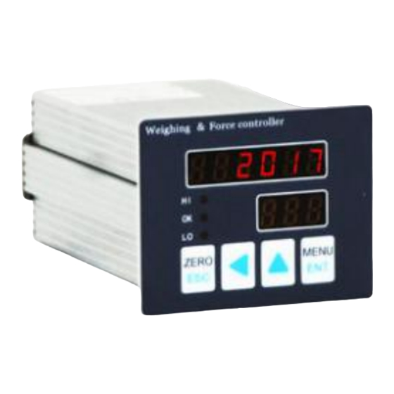
Page 20: Description Of Panel Operation15
3.2 Description of Panel Operation Clear/Return Key Data Adjustment Key ( Diagram 4 ) Shift Key Menu/Confirm Key 3.2.1 Description of Indicator Lamp HI: upper limit output indicator OK:medium limit output indicator LO: lower limit output indicator... -
Page 21: 3.2.2 Instructions For Keystrokes And Shortcut
3.2.2 Instructions for Keystrokes and Shortcut Operations : Short press to do zero clearing (in the main interface). After entering the sub-menu, short press to switch over the item. After entering the setting activation state, short press to cancel the activation state. In the sub-menu, long press the option button for three seconds to exit to the main interface. - Page 22 : Resize the data after entering the sub-menu. Select the main menu respectively after entering the first level menu. In the main interface, short press this button to select the display values in the upper row: real-time measured values, peak values, analog value, input state, output state.
-
Page 23: Chapter 4 Calibration18
Chapter 4 Calibration 4.1 Calibration of Sensor Weights (Main display interface) Long press for three seconds. Leave the sensor idle until the figures displayed in the next row keep stable, then short press to calibrate the zero point. Continued... - Page 24 Put the weights on the sensor device until the figures displayed in the next row keep stable, then short press Put the weights on the sensor device. Input the weight of the weights into the display window below, then short press Calibration with weights ends.
-
Page 25: Calibration Without Weights20
4.2 Calibration without Weights (Main display interface) Long press for three seconds. Leave the sensor idle until the figures displayed in the next row keep stable, then short press to calibrate the zero point. In this interface short press to enter... - Page 26 calibration without weights. Input the sensitivity of the sensor, then short press Input the range of the sensor, then short press Calibration without weights ends.
- Page 27 Chapter 5 Menu Details 5.1 Primary Menu ( Main display interface ) Long press for three seconds. ( Basic parameters ) Short press ( Functional parameters ) Short press...
- Page 28 ( Analog parameters ) Short press ( Port parameters ) Short press ( Communication parameters ) Short press to enter the sub-menu from the primary menu.
- Page 29 5.2 Sub-Menu 5.2.1 Basic Parameters Initi Parameter Parameter Value Code Name Explanation Range Valu The difference 1, 2, 5, Division between two 10, 20, Value adjacent display values Number of Decimal decimal places 0, 1, 2, 3, places of the display 4, 5 value The maximum...
- Page 30 The range of zero-setting operations when Zero range it powers on. 0-99999 Invalid when displayed as zero. ZLF: automatic Automatic zero range. 0-999 zero range ZLT: automatic zero-setting time. Let w be the weight value. Automatic When w meets zero-settin 0.0-9.9 ZLF>w>-ZLF g time...
- Page 31 and keeps stable, the machine will be automatically set to zero. The range to judge if the data Stability is stable. To be 0-99 range dynamic when it is out of this range. The time that it Stability takes to judge if 0.0-9.9 time the data is stable...
- Page 32 frequency conversion 50, 100 The ability to reduce Filtering fluctuations in 0-19 coefficient unstable weighing data Negative Display negative OFF/ON display value or not 5.2.2 Functional Parameters Parameter Parameter Value Initial Code Name Explanation Range Value Formula Number of the number formula Lower...
- Page 33 Medium Limits for limit comparison and 0-99999 2000 value judgment Upper Limits for limit comparison and 0-99999 6000 value judgment 0: continuous comparison; 1: automatic comparison; 2: external input Ways of triggering 0, 1, 2, comparis comparison; 3, 4 3: 1 and 2; 4: external input start-stop comparison.
- Page 34 compare is selected as 1, triggering comparison values occurs at the point the value is greater than this setting value. When the judgment mode is selected as 1 Comparis or 2, the 0.00-20. 0.00 on delay judgment signal is output after the delay comparison.
- Page 35 judgment. See note 3 The threshold at which the Peak reset displayed peak 0-99999 threshold value can be updated. 0: real-time value Comparis 1: peak value 0, 1, 2 on source 2: negative peak value Limit output time. 0.0 means the output is in Output progress all the...
- Page 36 source 1: negative peak 2: positive and negative peak 5.2.3 Analog Parameters Parameter Parameter Value Initial Code Name Explanation Range Value Analog Calibration for 4mA DA 0-32767 6554 4mA point value Analog Calibration for 3276 20mA 0-39999 20mA point DA value 0-20 type: 0-20, Analog...
- Page 37 0 point is 10mA 4-12-20 type: 0 points is 12mA Positive or -99999 weight negative weight value can be input 99999 20mA The weight value point 0-99999 5000 of 20mA current weight output value 5.2.4 Port Parameters Parameter Parameter Value Initial Code Name...
- Page 38 5:clear the peak value; 6: lock button; 7: start to compare; 8: stop comparing OUT1 0: communication function settings; 1: the lower limit; OUT2 2: the middle limit; function 3: the upper limit; OUT3 4: zero zone; function 7: stability. 5.2.5 Communication Parameters Parameter Parameter...
- Page 39 in serial port 4800, 9600, 19200, 38400 Data bit Data Stop bit format Check bit 0: MODBUS Ways of 1: continuous 0, 1, 2, communic mode ation 8: print The address of Communic the slave station ation when 1-128 address communicating with MODBUS Transmissi...
- Page 40 output in a continuous output format at communication mode 5.3 Examples of Modifying Parameters (Enumerate the modified division value A0 dd) ( Main display interface ) Long press for three seconds. ( Basic parameters ) Short press...
- Page 41 Short press to activate parameters in the next row. The figures in the upper row flicker. Short press to modify parameters. After modifying the parameters, short press to confirm and write. Long press for 3 seconds to return to the main display interface.
- Page 42 Chapter 6 Serial Communication 6.1 MODBUS Communication This controller supports the read/write function of register standard MODBUS-RTU network communication protocol in the master-slave form (supports function codes 03H, 10H). It is usually suitable for data exchange between a slave and a host in a bus network. If the address that is sent to the slave does not match or the CRC check error occurs, the slave will not respond.
- Page 43 register er of s (H) regist Read Command 03H Response Format Functi Byte Code Cont rolle Defini Data Data Check Check Data n tion 2...n-1 addr Write Command 10H Send Format Func tion High High segme segme ment Data segme nt of nt of Chec...
- Page 44 Write Command 10H Response Format Func tion Byte High High segme Cont segment segment segment nt of rolle of the Chec Defin Check number ition starting starting numbe addr address address r of registers register s (L) Example of debugging serial ports: read the real-time measured value ( Baud rate: 9600.
- Page 45 6.1.2 Comparison between Register Address and Data Table of Comparison between Register Address and Data Type of Description of Read Name Range Data (03H) and Write (10H) 0: 000000 1: 00000.0 2-byte Decimal 2: 0000.00 Read-write integer point 3: 000.000 4: 00.0000 5: 0.00000 4-byte...
- Page 46 zone; 1, in zero zone 00 bit: the lower limit 01 bit: the medium limit 02 bit: the upper limit 0: normal 2-byte State of 1: sensor error, integer sensor read-only 00 bit: OUT1 01 bit: OUT2 02 bit: OUT3 State of 08 bit: IN1 2-byte...
- Page 47 4-byte Lower long limit 0~999999 Read-write integer value 4-byte Medium long limit 0~999999 Read-write integer value 4-byte Upper long limit 0~999999 Read-write integer value 2-byte Division 1, 2, 5 Read-write integer Value 4-byte Full long 1~999999 Read-write range integer 4-byte Zero long 1~999999...
- Page 48 Zero 2-byte tracking 0~999 Read-write integer range Zero 2-byte tracking 0~99 Read-write integer time Calibrat ed value 2-byte 0~1000 Read-write integer current output Calibrat ed value 2-byte current 0~4095 Read-write integer 20mA output...
- Page 49 Compar 4-byte long 0~999999 Read-write triggerin integer g value 4-byte Peak long reset 0~999999 Read-write integer value Zero 00 bit: check the zero 2-byte and gain point. Write 1 valid integer check 01 bit: check the gain. trigger Write 1 valid 4-byte Weight long...
- Page 50 port. For example, the current data is displayed as +123456, then the controller sends the following data: ST, GS, +0123456[OD][OA] OL = overloaded, ST = stable, US = unstable, NT = net weight, GS = gross weight Chapter 7 Comment Declaration Note 1: explanation of communication data types The 2-byte integer data is 16-bit unsigned integer data;...
- Page 51 sub-menu is set to 0, this function is enabled. That is, the limit output is output with the real-time measured values displayed in the upper row. 2. Automatic comparison function: When the "comparison mode" of the functional parameters in the sub-menu is set to 1, this function is enabled.
- Page 52 upper/lower stations that fail to complete the output ) 4. Peak comparison function: When "judgment source" of the functional parameters in the sub-menu is set to 1, this function is enabled. When the “comparison mode” is selected as 0, the limit output is output with the real-time measured values displayed in the lower row.
- Page 53 Note 3:explanation of the judgment method (X is the real-time weight value or peak value) Ways Lower Limit Medium X< Lower <X Limit <X Upper judg Limit <Medium <Upper Limit <X ment Limit Limit Lower Medium Upper limit limit No output limit output output output...
- Page 54 Note 4. Operation method of restoring factory settings Press to boot. When the interface is displayed as (Figure 5), release , enter "000111" and then press to restore the factory default parameters. (Calibration results will not be restored) ( Diagram 5 )
- Page 55 Note 5. Fault alarm information and troubleshooting This error alarm is an overload fault. Please check if the sensor is overloaded or increase the full range. This error alarm is a sensor fault or AD fault. Please check if there is any problem in sensor wiring, and replace the sensor or controller.
- Page 56 Note 6. The shortcut function of the digital adjustment key (Main display interface) Short press (Peak value display) Short press (4-20ma analog display)
- Page 57 Short press (I/O input port state) Short press (I/O output port state) Short press (Main display interface)
- Page 58 Note 7. Zero point state & stable state display notes (Bottom digital tube display) (at zero point state) (in a stable state)
- Page 59 Note 8. Comparison table of figures and letters display...
Need help?
Do you have a question about the AD2017D and is the answer not in the manual?
Questions and answers