
Related Manuals for Strasbaugh 7AA

Summary of Contents for Strasbaugh 7AA
- Page 1 Model 7AA Wafer Grinder Operation Maintenance Manual S T R A S B A U G H 825 Buckley Road San Luis Obispo, CA 93401 Phone: (805) 541-6424 Fax: (805) 541-6425 Version 1.2 - April 18, 1996...
- Page 2 Copyright © 1996 by Strasbaugh. All rights reserved.
-
Page 3: Table Of Contents
Strasbaugh Table of Contents Table of Contents Chapter 1 Introduction 1 - 1 About the 7AA Manual About the Model 7AA Wafer Grinder Guarantee/Warranty Certificate Safety General Operation Visual Hazard Alerts Hazard Magnitude Levels Three-Panel Alert Graphics Interlocks - Safety Interlock Door Switches... - Page 4 Operation and Maintenance Manual Model 7AA Wafer Grinder Chapter 3 Machine Description 3 - 1 Control System Overview Power Distribution Servo Control Loop 24 VDC Inputs 24 VDC Outputs AC Outputs CRT Video Mechanical Overview Grind Assembly Bed Work Spindle Carriage...
- Page 5 Strasbaugh Table of Contents Chapter 5 Machine Setup 5 - 1 Machine Parameter Entry Adjust R.P.M.'S Chapter 6 Preventive Maintenance 6 - 1 Daily Preventive Maintenance Weekly Preventive Maintenance Schedule Monthly Preventive Maintenance Schedule Chapter 7 Mechanical Maintenance Procedures 7 - 1...
- Page 6 Operation and Maintenance Manual Model 7AA Wafer Grinder Chapter 8 Software Calibration Procedures 8 - 1 Machine Diagnostics Offline Storage Support Utilities Installation Operating Instructions Transfer Grind Parameters From Machine To Disk 'F1' Transfer Grind Parameters From Disk To Machine 'F2'...
- Page 7 Strasbaugh Table of Contents Chapter 10 Troubleshooting 10 - 1 Frequently Encountered Problem Conditions Error Conditions And Messages Error Condition Lights Servo Error Codes Appendices Engineering Drawings Part Lists Safety Reference Manufacturers’ Data Version 1.2 - April 18, 1996; Update 11/6/96...
- Page 8 Operation and Maintenance Manual Model 7AA Wafer Grinder This page intentionally left blank. viii U Version 1.2 - April 18, 1996; Update 11/6/96...
- Page 9 Strasbaugh “generic” safety information package was incorporated in Chapter 1 (Introduction). • Multiple references were added directing users to Strasbaugh 7AA maintenance video three- volume set and Giddings and Lewis PiC409 Family User’s Manual. 7AA Operation/Maint. Manual Vers. 1.2; Revision Record No. O/M-1.1, 4/18/96...
- Page 10 • Version 1.2 - 4/18/96 (168 pp. of text - (Version 1.1 - undated) title pages, detailed table of contents, chapters 1 through 10, appendices) 7AA Operation/Maint. Manual Vers. 1.2; Revision Record No. O/M-1.1, 4/18/96 Page - 2 of 2...
- Page 11 (Version 1.2 - April 18, 1996; Update 11/6/96) Item: Changes to main Table Of Contents reflecting addition of MSDS sheets for Shell Tellus (R) Oil 10 to Safety section. 7AA Operation/Maint. Manual Vers. 1.2; Revision Record No. O/M-1.1, 11/6/96 Page - 1 of 2...
- Page 12 • Shell Tellus (R) Oil 10 MSDS sheets (8 pp.) Note: Insert immediately after page 1-30U. Item: Addition of MSDS sheets for Shell Tellus (R) Oil 10 to Safety section. 7AA Operation/Maint. Manual Vers. 1.2; Revision Record No. O/M-1.1, 11/6/96 Page - 2 of 2...
-
Page 13: Chapter 1 Introduction
Strasbaugh Introduction Introduction • ABOUT THE 7AA MANUAL • ABOUT THE MODEL 7AA WAFER GRINDER • GUARANTEE/WARRANTY • SAFETY Version 1.2 - April 18, 1996; Update 11/6/96 1 - 1 U... - Page 14 Operation and Maintenance Manual Model 7AA Wafer Grinder ABOUT THE 7AA MANUAL ABOUT THE MODEL 7AA WAFER GRINDER GUARANTEE/WARRANTY CERTIFICATE SAFETY General Operation Visual Hazard Alerts Hazard Magnitude Levels Three-Panel Alert Graphics Interlocks - Safety Interlock Door Switches Sprayer Use...
-
Page 15: About The 7Aa Manual
In addition to the information listed in this manual, refer also to the following when performing adjustments to the 7AA: • the Strasbaugh 7AA Maintenance Videos (a three-volume set). • the Giddings and Lewis PiC409 Family User’s Manual. Version 1.2 - April 18, 1996; Update 11/6/96... -
Page 16: About The Model 7Aa Wafer Grinder
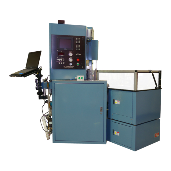
The two step grind, with coarse and fine grit wheels concentrically mounted, may do both rapid stock removal and fine finishing in a single wafer handling operation. The 7AA’s anti- deflection construction features a heavy duty cast iron column and head rigidly secured to a steel weldment base which runs the length of the machine. -
Page 17: Guarantee/Warranty Certificate
Strasbaugh Introduction GUARANTEE/WARRANTY CERTIFICATE Version 1.2 - April 18, 1996; Update 11/6/96 1 - 5 U... - Page 18 Operation and Maintenance Manual Model 7AA Wafer Grinder This page intentionally left blank. 1 - 6 U Version 1.2 - April 18, 1996; Update 11/6/96...
-
Page 19: Safety
A checklist of basic safety instructions addresses general operation. The visual hazard alerts section explains the system of hazard alert graphics used in Strasbaugh manuals and on the machines themselves. The section on safety interlock door switches reviews machine motion shutdown/suspension interlocks designed to take effect when machine cabinet doors are opened. -
Page 20: General Operation
Operation and Maintenance Manual Model 7AA Wafer Grinder GENERAL OPERATION The Strasbaugh polishing, grinding, lapping, and cutting machines have been designed for safe operation. However, caution should be exercised while operating this machine. Failure to adhere to the following safety instructions and to good safety practices may result in injury to personnel or damage to the machine. - Page 21 Strasbaugh Introduction • Recommendation Only! Avoid long term exposure to low- frequency electromagnetic fields. The data concerning low- frequency electromagnetic health effects is inconclusive, but a 1995 IEEE engineering publication recommends “prudent avoidance” of prolonged and continuous exposure. Maintenance personnel are advised to avoid standing at open power panel doors for extended periods with the power on.
-
Page 22: Visual Hazard Alerts
Operation and Maintenance Manual Model 7AA Wafer Grinder VISUAL HAZARD ALERTS To aid the user in safe operation of Strasbaugh machines, visual hazard alert graphics are placed in appropriate locations throughout the operation and maintenance manuals and on the machines themselves. -
Page 23: Three-Panel Alert Graphics
HREE ANEL LERT RAPHICS The three-panel alert graphics used in the Strasbaugh manuals are composed of a keyword; a hazard symbol; and a text box identifying the hazard, the result(s) of ignoring the hazard, and instructions on avoiding the hazard. - Page 24 Operation and Maintenance Manual Model 7AA Wafer Grinder Alert Graphic: Symbol: • pinch points When To Be Aware: • whenever machine parts are moving. • anytime immediately before and during auto mode operation. • anytime immediately before and during manual operation.
- Page 25 Strasbaugh Introduction Alert Graphic: Symbol: • pinch points When To Be Aware: • while the table is being removed or installed. • when moving the machine or associated equipment (as in during installation). Notes: Lifting the polish table(s) presents the potential for a lifting strain hazard;...
- Page 26 Operation and Maintenance Manual Model 7AA Wafer Grinder Alert Graphic: Symbol: • chemical hazard When To Be Aware: • anytime during operation and maintenance of machine. Alert Graphic: Symbol: • hot surface When To Be Aware: • while changing the polish pad.
-
Page 27: Interlocks - Safety Interlock Door Switches
Introduction INTERLOCKS - SAFETY INTERLOCK DOOR SWITCHES Operator and service doors on Strasbaugh machines are equipped with interlock safety switches. One or more open interlocks interrupt(s) the auto cycle, inhibit the servos, or remove electrical power via the EMO circuit. -
Page 28: Sprayer Use
Be sure to follow all local, state, and federal regulations regarding personnel safety and waste disposal. Refer to suppliers’ material safety data sheets. WASTE DISPOSAL For all chemicals used with Strasbaugh machines: • Be aware of any personnel safety hazards. Refer to chemical suppliers’ material safety data sheets (MSDS). -
Page 29: Lockout Safety Procedure
Strasbaugh Introduction LOCKOUT SAFETY PROCEDURE (Reproduce for shop copy. Fill-in data or check off as appropriate.) EQUIPMENT LOCATION: MODEL 7AA SERIAL NUMBER: MANUFACTURER: Strasbaugh, Inc. PROCEDURE AUTHORIZED BY: DATE: PHONE: DEPARTMENT: OSHA regulations state that "The procedures shall clearly and specifically outline the scope,... -
Page 30: Lockout Procedure
Model 7AA Wafer Grinder LOCKOUT PROCEDURE • Per ANSI Z244.1-1982 • Lockout procedure for Strasbaugh Polishing, Lapping, Grinding, and Cutting Machines Purpose This procedure establishes the minimum requirements for lockout of energy sources that could cause injury to personnel. All maintenance personnel, operators, and machine owner employees shall comply with the procedure. - Page 31 Strasbaugh Introduction 3. For each energy source, operate the switch, valve, or other energy isolating device so that the energy source(s) (electrical, mechanical, hydraulic, etc.) is disconnected or isolated from the equipment. Stored energy, such as that in capacitors, springs, elevated machine members, rotating flywheels, hydraulic systems, and air, gas, steam, or water pressure.
-
Page 32: Appendix To Lockout Safety Procedure
Operation and Maintenance Manual Model 7AA Wafer Grinder PPENDIX TO OCKOUT AFETY ROCEDURE 29 CFR 1910.147 RAINING OCKOUT AGOUT Introduction On October 30, 1989, the Lockout/Tagout Standard, 29 CFR 1910.147, went into effect. It was created to help reduce the death and injury rate caused by the unexpected energization or startup of machines, or the release of stored energy. - Page 33 Strasbaugh Introduction Written Program OSHA 29 CFR 1910.147 (c)(4) covers the minimal acceptable written program procedures. It must include: 1. A specific written statement of the intended use of the procedure. 2. Specific procedural steps are taken for shutting down, isolating, blocking and securing machines or equipment to control hazardous energy.
-
Page 34: Gallium Arsenide And Germanium Use
Operation and Maintenance Manual Model 7AA Wafer Grinder GALLIUM ARSENIDE AND GERMANIUM USE The information below is applicable only to owners of Strasbaugh machines using gallium arsenide or germanium in their processes. NOTICE: Material safety data sheets (MSDS) for gallium arsenide and germanium are to be provided by the supplier of the wafers/wafer crystals. - Page 35 Strasbaugh Introduction Skin Contact If skin contact occurs, remove contaminated clothing and flood skin with large amounts of water. The following effects may result: skin irritation, dermatitis and possible skin sensitization, pigmentation, and/or hyperkeratosis. If irritation persists, seek medical attention.
- Page 36 Operation and Maintenance Manual Model 7AA Wafer Grinder Fire and Explosion Hazards In the event of a fire, firefighters should use normal procedures which include wearing NIOSH/MSHA approved self-contained breathing apparatus. Flame and chemical resistant clothing, hats, boots, and gloves should also be worn. Do not use water to extinguish the gallium arsenide.
- Page 37 Strasbaugh Introduction In the event of a spill or leak, the company’s Hazardous Materials Response Team should be notified. While wearing full protective equipment, the response team should cover the spill with dry sand, vermiculite, or any other approved absorbent material. Mix well and carefully transfer the contaminated absorbent material to an approved container used only for gallium arsenide waste.
-
Page 38: Germanium (Ge)
Operation and Maintenance Manual Model 7AA Wafer Grinder ERMANIUM Germanium is used in the semiconductor industry in the form of polished wafers. “Germanium crystals are grown in rods up to 1-3/8 in. (3.49 cm) in diameter for use in making transistor wafers. High-purity crystals are used for both P and N semiconductors. - Page 39 Strasbaugh Introduction Special Protection At a minimum, the following items should be worn when handling germanium: lab coat and apron, rubber protective gloves, and ANSI approved safety goggles. Additionally, an eyewash station capable of sustained flushing must be available. A safety drench shower and hygienic facilities for washing should be located nearby.
- Page 40 Operation and Maintenance Manual Model 7AA Wafer Grinder Reactivity Warnings When heated, germanium is incompatible with bromine, chlorine, fluorine, oxygen, potassium chloride, and potassium. Additionally, mixing with aqua regia, concentrated nitric or sulfuric acids, fused alkalies, nitrates or carbonates, halogens, and oxidants should be avoided.
- Page 41 Strasbaugh Introduction Environmental Information During wafer processing, the wastewater generated must be monitored- -it cannot be allowed to flow freely into an open drain. Consult local, state, or federal EPA regulations for proper disposal. The wastewater may be collected in compatible 55-gallon drums for waste disposal through a licensed facility.
-
Page 42: Material Safety Data Sheets For Products Used In Machine Maintenance
MATERIAL SAFETY DATA SHEETS FOR PRODUCTS USED IN MACHINE MAINTENANCE This section contains Material Safety Data Sheets (MSDS) for products recommended by Strasbaugh for use in machine maintenance. The product names are listed immediately below: • Shell Tellus (R) Oil 10 1 - 30 U Version 1.2 - April 18, 1996;... -
Page 43: Chapter 2 Installation
Strasbaugh Installation Installation • RECEIVING • LOCATION • LEVELING • FACILITIES REQUIREMENTS Version 1.2 - April 18, 1996 2 - 1... - Page 44 Operation and Maintenance Manual Model 7AA Wafer Grinder RECEIVING LOCATION LEVELING FACILITIES REQUIREMENTS 2 - 2 Version 1.2 - April 18, 1996...
- Page 45 Strasbaugh Installation INSTALLATION Notes When performing any adjustments on the Model 7AA, in addition to the information listed below in this chapter, refer also to the following: • the Strasbaugh 7AA Maintenance Videos (a three-volume set). • the Giddings and Lewis PiC409 Family User’s Manual.
-
Page 46: Receiving
Operation and Maintenance Manual Model 7AA Wafer Grinder RECEIVING The machine should be inspected for any damage that may have occurred during shipping. Any such damage should be noted and must be corrected before proceeding with the installation of the machine. -
Page 47: Location
Strasbaugh Installation LOCATION The location for the machine requires a flat stable surface (e.g. concrete slab) with a minimum of three feet of clearance around the perimeter of the machine. It should be as close as possible to required connections and allow sufficient space for operator movement. -
Page 48: Facilities Requirements
An isolated vacuum pump with self contained drain system is available from Strasbaugh as a machine option. For use with facility vacuum supply a wall mountable vacuum/waste separator is also available. -
Page 49: Machine Description
Strasbaugh Machine Description Machine Description • CONTROL SYSTEM OVERVIEW • MECHANICAL OVERVIEW • PNEUMATIC/FLUID SYSTEM OVERVIEW Version 1.2 - April 18, 1996 3 - 1... -
Page 50: Control System Overview Power Distribution Servo Control Loop
Operation and Maintenance Manual Model 7AA Wafer Grinder CONTROL SYSTEM OVERVIEW POWER DISTRIBUTION SERVO CONTROL LOOP 24 VDC INPUTS 24 VDC OUTPUTS AC OUTPUTS CRT VIDEO MECHANICAL OVERVIEW GRIND ASSEMBLY BED WORK SPINDLE CARRIAGE GRIND SPINDLE SUPPORT GRIND SPINDLE FEED MECHANISM... - Page 51 Strasbaugh Machine Description MACHINE DESCRIPTION CONTROL SYSTEM OVERVIEW This section is intended to provide a general description of the electrical control system as an aid in understanding the operation and maintenance of the machine. For specific details regarding this discussion refer to the electrical schematics and component assembly drawings in the back of this manual.
-
Page 52: 24 Vdc Inputs
Operation and Maintenance Manual Model 7AA Wafer Grinder Line voltage is stepped down through a 2:1 750 VA transformer to supply the AC voltage to power a rectified DC bus capacitor on the servo amplifier. Also, line voltage is connected to the fan/bias power connection on the servo amplifier. -
Page 53: 24 Vdc Outputs
Strasbaugh Machine Description The model 7AA uses both sinking and sourcing inputs. With sinking inputs the positive input terminal (positive input terminals correspond to pins identified by letters on the input card edge connector) is connected to +24 VDC and the input turns on when... -
Page 54: Crt Video
Operation and Maintenance Manual Model 7AA Wafer Grinder Refer to the Giddings & Lewis manual for a more complete description and schematic of the AC output modules. CRT VIDEO The video system consists of two video modules in the programmable control and the operator panel CRT display. -
Page 55: Mechanical Overview
Machine Description MECHANICAL OVERVIEW This section describes the fundamental principles of the mechanics of the grind operation for the 7AA. The mechanical functions consist of the grind assembly bed, work spindle carriage, grind spindle support, and grind spindle feed mechanism. The... -
Page 56: Grind Spindle Feed Mechanism
Operation and Maintenance Manual Model 7AA Wafer Grinder crossmember on the bed. The rear of the upright is secured by a nut affixed to the rear end of the bed. The forward-rear tilt of the spindle is adjusted by rotating the upright bolt through the nut. -
Page 57: Pneumatic/Fluid System Overview
Strasbaugh Machine Description PNEUMATIC/FLUID SYSTEM OVERVIEW The machine requires clean dry air, vacuum, deionized (DI) water and tap water for all pneumatic/fluid functions. Clean dry air is connected to the air supply connection on the back of the machine. A ball valve provides for shutting off air to the machine. - Page 58 Operation and Maintenance Manual Model 7AA Wafer Grinder Vacuum is connected from the rear of the machine to the pneumatic panel. A gauge on the operator panel indicates the vacuum level at the supply connection. Six vacuum valves (designated SOL15-SOL20) control the vacuum functions on the machine.
-
Page 59: Operator Functions
Strasbaugh Operator Functions Operator Functions • MACHINE OPERATION DESCRIPTION • CONTROL PANEL • CRT DISPLAY MENUS • BASIC OPERATION Version 1.2 - April 18, 1996 4 - 1... -
Page 60: Machine Operation Description
Operation and Maintenance Manual Model 7AA Wafer Grinder MACHINE OPERATION DESCRIPTION OVERVIEW - MACHINE CYCLE SEQUENCE WITH WAFER TRANSPORT SYSTEM WAFER TRANSPORT SYSTEM MACHINE CYCLE SEQUENCE WITHOUT WAFER TRANSPORT SYSTEM CONTROL PANEL CRT DISPLAY MENUS SPECIAL KEY FUNCTIONS BASIC OPERATION... - Page 61 Strasbaugh Operator Functions OPERATOR FUNCTIONS MACHINE OPERATION DESCRIPTION OVERVIEW - MACHINE CYCLE SEQUENCE WITH WAFER TRANSPORT SYSTEM The basic machine cycle consists of the following sequence of events: 1) Send wafer - the send wafer transport system locates the first...
- Page 62 Operation and Maintenance Manual Model 7AA Wafer Grinder 6) Pick and place (rinse/spin station to measurement station) - the pick and place positions the #3 vacuum chuck to lift the wafer from the rinse/spin chuck and deposit it at the measurement station.
- Page 63 Strasbaugh Operator Functions WAFER TRANSPORT SYSTEM The machine uses two send elevators and two receive elevators coupled with a three-arm two-position pick and place assembly to provide efficient, continuous movement of wafers through the cycle. The transport system contains the mechanics and necessary motors, switches and sensors to perform its operation.
- Page 64 Operation and Maintenance Manual Model 7AA Wafer Grinder An elevator will not service a cassette unless the empty cassette has been removed and a new cassette replaced. A "cycle halt" condition will inhibit the send elevators from lowering to the next occupied slot.
- Page 65 Strasbaugh Operator Functions Halting the auto cycle will cause the elevators to continue their present function - looking for a wafer or raising to the upper travel limit - and will stop when completed. Removing a cassette at any time will cause the elevator to raise to its upper travel limit.
- Page 66 MACHINE CYCLE SEQUENCE WITHOUT WAFER TRANSPORT SYSTEM The manual version of the 7AA contains identical hardware used for the wafer grinding operation as the automatic version. However, the wafer transport system, including send elevators, centering station, pick and place assembly, rinse/spin station, and receive elevators is omitted.
- Page 67 Strasbaugh Operator Functions CONTROL PANEL The machine control panel provides the necessary indicators, displays and controls to allow the operator to monitor and control critical machine functions. The basic features of the control panel are explained below. 1) CRT display - used to display machine control and operating information as instructed by the control program.
- Page 68 Operation and Maintenance Manual Model 7AA Wafer Grinder CRT DISPLAY MENUS Machine control parameters are divided into and accessed via CRT display menus. The ten different menus are listed below: Menu Where To Find Details - Manual Location 1) Machine operation menu •...
- Page 69 Strasbaugh Operator Functions SPECIAL KEY FUNCTIONS Certain keys are programmed to perform specific functions depending on the present mode of operation. The special functions available in each mode are described below: all modes: [^] key prompts a thickness measurement [^] key and [0] key zero measurement probe...
- Page 70 Operation and Maintenance Manual Model 7AA Wafer Grinder dual grind mode: [START] key starts auto cycle [STOP] key halts auto cycle [ENT] key moves wafer from measurement station to active receive cassette machine diagnostics: [.] key returns to machine control menu 4 - 12 Version 1.2 - April 18, 1996...
- Page 71 Troubleshooting chapter of this manual. SUMMARY The list below is a summary of the procedures needed to start up the 7AA and complete an automatic grind cycle. The sections following provided detailed information on each. Machine power up. Machine initialization.
-
Page 72: Step 1 - Machine Power Up
Operation and Maintenance Manual Model 7AA Wafer Grinder STEP 1 - MACHINE POWER UP When all external connections to the machine are complete the machine may be powered-up. To turn on power to the machine, turn the door disconnect switch on the rear enclosure to "on."... -
Page 73: Step 2 - Machine Initialization
Strasbaugh Operator Functions STEP 2 - MACHINE INITIALIZATION Machine initialization is a self-contained routine designed to perform machine calibration with minimal operator intervention. The initialization routine performs three basic functions: 1) find home position for work chuck, 2) find position of coarse grinding wheel, and 3) find position of finish grinding wheel. - Page 74 Operation and Maintenance Manual Model 7AA Wafer Grinder The display will read: initializing work chuck axis The work chuck will begin moving toward its home position (out). At the same time the grind spindle will raise to its upper limit. The send elevator will move down to locate the test wafer then transport the wafer to the pick-up station.
-
Page 75: Step 3 - Grind Parameter Entry
Strasbaugh Operator Functions STEP 3 - GRIND PARAMETER ENTRY The grind parameter entry menu is used to access the variable data that defines the necessary parameters for a grind cycle. These parameters are a function of many variables and depend on the particular process or application. - Page 76 Operation and Maintenance Manual Model 7AA Wafer Grinder Rapid feed thickness - enter the thickness (in microns) to which the grind wheel will use the rapid feed rate. Below this thickness the final feed rate will be used. The computer automatically computes this number as...
- Page 77 Strasbaugh Operator Functions DUAL GRIND - COARSE PARAMETERS This menu defines the parameters for the coarse grind portion of a dual grind cycle. The finish wheel will grind the wafer after the coarse wheel portion of the dual grind cycle. The parameters used for the dual grind - coarse menu are identical to those for the single grind menu (see preceding section).
- Page 78 Operation and Maintenance Manual Model 7AA Wafer Grinder Coarse dwell time - enter the dwell time in tenths of a second. This is the amount of time that the coarse wheel will remain at the coarse wafer thickness before ending the grind cycle.
- Page 79 Strasbaugh Operator Functions Finish feed rate - enter the final feed rate for the fine wheel in tenths of microns/second (e.g. for 1.0 microns/second enter 10). This is the feed rate that will be used for stock removal between the rapid fine thickness and the finish wafer thickness.
-
Page 80: Step 4 - Grind Mode Selection
Operation and Maintenance Manual Model 7AA Wafer Grinder STEP 4 - GRIND MODE SELECTION The grind mode select menu is used to select a single or dual grind cycle. After all grind parameters are valid the auto cycle can be initiated by selecting one of the two grind cycles. -
Page 81: Step 5 - Place Cassettes On Elevators
Strasbaugh Operator Functions STEP 5 - PLACE CASSETTES ON ELEVATORS Place cassettes loaded with wafers on the send elevators and empty cassettes on the receive elevators. Version 1.2 - April 18, 1996 4 - 23... -
Page 82: Step 6 - Start Machine Auto Cycle
Operation and Maintenance Manual Model 7AA Wafer Grinder STEP 6 - START MACHINE AUTO CYCLE After all parameters have been correctly entered, the machine is ready to run in the auto cycle mode. Select the desired grind mode. Send and receive cassettes should be in place. -
Page 83: Machine Setup
Strasbaugh Machine Setup Machine Setup • MACHINE PARAMETER ENTRY • ADJUST R.P.M.'S Version 1.2 - April 18, 1996 5 - 1... - Page 84 Operation and Maintenance Manual Model 7AA Wafer Grinder MACHINE PARAMETER ENTRY ADJUST R.P.M.'S 5 - 2 Version 1.2 - April 18, 1996...
-
Page 85: Machine Parameter Entry
Strasbaugh Machine Setup MACHINE SETUP MACHINE PARAMETER ENTRY The machine parameter mode is used to define certain parameters characteristic to specific machines and processes. These parameters usually must be determined empirically under actual process conditions. The accuracy of the machine parameter data is essential to establishing and maintaining optimum machine performance. - Page 86 Operation and Maintenance Manual Model 7AA Wafer Grinder Finish wear correction - enter the thickness in microns to compensate for finish wheel wear. This parameter is analogous to item 1 above but applied to the finish grind cycle. Finish wear limit - enter the accumulated thickness in microns to prompt finish wheel wear correction by the computer.
-
Page 87: Adjust R.p.m.'s
Strasbaugh Machine Setup ADJUST R.P.M.'S To display the machine operation menu, press the reset key. Turn the key switch to "PROG" and press the "8" key. This will display the R.P.M. settings menu. This menu lists six options: Grind spindle coarse... - Page 88 Operation and Maintenance Manual Model 7AA Wafer Grinder This page intentionally blank. 5 - 6 Version 1.2 - April 18, 1996...
-
Page 89: Preventive Maintenance
Strasbaugh Preventive Maintenance Schedules Preventive Maintenance Schedules • DAILY • WEEKLY • MONTHLY Version 1.2 - April 18, 1996 6 - 1... - Page 90 Operation and Maintenance Manual Model 7AA Wafer Grinder DAILY PREVENTIVE MAINTENANCE WEEKLY PREVENTIVE MAINTENANCE SCHEDULE MONTHLY PREVENTIVE MAINTENANCE SCHEDULE 6 - 2 Version 1.2 - April 18, 1996...
-
Page 91: Daily Preventive Maintenance
Strasbaugh Preventive Maintenance Schedules PREVENTIVE MAINTENANCE SCHEDULES DAILY PREVENTIVE MAINTENANCE Date: ________________ Machine Number: ________________ Fab Number: ________________ Tech. Initials 1. Make sure that diamond wheel is NOT spinning. __________ 2. Rinse grind chamber. __________ Version 1.2 - April 18, 1996... -
Page 92: Weekly Preventive Maintenance Schedule
Operation and Maintenance Manual Model 7AA Wafer Grinder WEEKLY PREVENTIVE MAINTENANCE SCHEDULE Date: ________________ Machine Number: ________________ Fab Number: ________________ Tech Initials 1. Complete daily P.M. _______ 2. Clean all optical and capacitive sensors on elevators. _______ 3. Clean optical fibers at measure station. - Page 93 Strasbaugh Preventive Maintenance Schedules 12. Measure diamond depths of wheel: _______ fine wheel _______ coarse wheel _______ fine wheel replaced? yes ____ no____ coarse wheel replaced? yes ____ no____ 13. Adjust spin chuck brush or water pressure. _______ 14. Adjust work chuck brush or water pressure.
-
Page 94: Monthly Preventive Maintenance Schedule
Operation and Maintenance Manual Model 7AA Wafer Grinder MONTHLY PREVENTIVE MAINTENANCE SCHEDULE Date: ________________ Machine Number: ________________ Fab Number: ________________ Tech. Initials 1. Complete daily P.M. _______ 2. Complete weekly P.M. _______ 3. Check cooling holes: coarse wheel _______ _______... - Page 95 Strasbaugh Preventive Maintenance Schedules 6. Inspect and check flatness of work chuck: flatness______inches was chuck ground? yes____ no____ surface of work chuck o.k.? yes____ no____ 7. Clean micrometer lever and mounting hardware. _______ 8. Clean exhaust plenum. _______ 9. Ensure that P.M. checklist and logbook are filled out properly.
- Page 96 Operation and Maintenance Manual Model 7AA Wafer Grinder This page intentionally blank. 6 - 8 Version 1.2 - April 18, 1996...
-
Page 97: Chapter 7 Mechanical Maintenance Procedures
Strasbaugh Mechanical Maintenance Procedures Mechanical Maintenance Procedures • MANUAL CONTROL OF MACHINE • GRIND OPERATION PROCEDURES • ELEVATOR CALIBRATION • LUBRICATION Version 1.2 - April 18, 1996 7 - 1... - Page 98 Operation and Maintenance Manual Model 7AA Wafer Grinder MANUAL CONTROL OF MACHINE GRIND OPERATION PROCEDURES SPINDLE SPEED SETTINGS GRIND WHEEL REPLACEMENT WHEEL TRUING AND DRESSING GRIND WHEEL COOLANT WORK CHUCK REPLACEMENT WORK CHUCK GRINDING CHUCK GRIND MODE PROCEDURE GRIND SPINDLE ALIGNMENT...
- Page 99 Assumption The procedures below were written with the assumption that the reader is thoroughly familiar with the 7AA Wafer Grinder. If not, read the chapters in this manual on Machine Description, Installation, Operator Functions, and Machine Setup before beginning any procedure.
-
Page 100: Manual Control Of Machine
Operation and Maintenance Manual Model 7AA Wafer Grinder MANUAL CONTROL OF MACHINE The manual jog mode provides manual operator control of both servo axes and the pick and place rotation. These functions are normally used to assist in maintaining and servicing the machine. - Page 101 Strasbaugh Mechanical Maintenance Procedures 1 - work chuck jog speed fast/slow 4 - work chuck rinse (then press "f" to scrub work chuck) [+/-] - turn work chuck vacuum on/off [.] - raise/lower grind hood door The grind wheel spindle will rise to a safe height above the wafer chuck once the [R] key is pressed to exit the manual jog mode.
-
Page 102: Grind Operation Procedures
Operation and Maintenance Manual Model 7AA Wafer Grinder GRIND OPERATION PROCEDURES There are many adjustment, calibration and compensation procedures that play an important role in maintaining optimal performance of the wafer grinding operation. This section provides a description of these procedures and how to implement them for maximum results. -
Page 103: Grind Wheel Replacement
Strasbaugh Mechanical Maintenance Procedures GRIND WHEEL REPLACEMENT Periodic inspection of the grinding wheels should be implemented to determine when wheels are worn and require replacement. Each wheel has 1/8" of diamond bond when new. The bond will wear until the aluminum hub is exposed. Wheels will not grind once the aluminum has been exposed. -
Page 104: Wheel Truing And Dressing
Operation and Maintenance Manual Model 7AA Wafer Grinder WHEEL TRUING AND DRESSING Grind wheels require truing and dressing for proper operation. Truing is required to remove any runout on the wheel surface once the wheel is fastened to the mounting surface. Dressing prepares the wheel for grinding by removing the surface layer of the bond and exposing a clean diamond layer. - Page 105 Strasbaugh Mechanical Maintenance Procedures This can be done by carefully pushing the pick and place 2 chuck down on the work chuck and releasing. An alternative to the manual dressing operation above is to grind the disk as a wafer using the auto cycle. This requires a disk mounted on a pad that is compatible with the wafer transport system.
-
Page 106: Grind Wheel Coolant
Operation and Maintenance Manual Model 7AA Wafer Grinder GRIND WHEEL COOLANT The coolant for each grind wheel is delivered from spouts located above the wheel mounting plate. The coolant flows into rings mounted on the plate to contain the coolant. Holes drilled through the plate allow the coolant to fall onto the wafer while grinding. -
Page 107: Work Chuck Replacement
Strasbaugh Mechanical Maintenance Procedures WORK CHUCK REPLACEMENT The work chuck is a porous ceramic material bonded to a stainless steel mounting flange. The chuck has approximately 5/8" of usable depth. Once the chuck surface is low enough the wheels and/or pick and place chucks will no longer reach the wafer. -
Page 108: Work Chuck Grinding
Operation and Maintenance Manual Model 7AA Wafer Grinder WORK CHUCK GRINDING CHUCK GRIND MODE The chuck grind mode may be used for two specific functions: 1) to grind the work chuck and 2) to dress either grinding wheel with a dressing disk. -
Page 109: Procedure
Strasbaugh Mechanical Maintenance Procedures As mentioned in the preceding section the chuck vacuum and grind hood door can be controlled manually using the [+/-] and [.] keys, respectively. The vacuum is required to secure a dressing disk for wheel dressing. The door must be lowered to prevent coolant water from escaping while grinding. -
Page 110: Grind Spindle Alignment
Operation and Maintenance Manual Model 7AA Wafer Grinder GRIND SPINDLE ALIGNMENT The alignment between the work and grind spindles is critical to machine performance. Mechanical adjustments are provided for precise alignment in two planes of the upper grind spindle position. - Page 111 Strasbaugh Mechanical Maintenance Procedures small steel plate on the wheel. This steel plate provides a mounting surface for a magnetic indicator base. Mount a dial indicator to measure the chuck surface as the indicator is swept side to side. The Y-Z plane adjustment consists of four clamp screws and two jack screws.
- Page 112 Operation and Maintenance Manual Model 7AA Wafer Grinder between the rear foot and the grind bed will change, thus adjusting the angle of the X-Z plane. To make the X-Z adjustment remove the exhaust plenum by removing the four hex head screws and sliding it out the back. The differential screw is held in position by a jam nut on each end.
-
Page 113: Spindle Pretravel Adjustment
Strasbaugh Mechanical Maintenance Procedures SPINDLE PRETRAVEL ADJUSTMENT The grind spindle feed mechanism has been explained previously. The rear contact point of the lever arm suspending the spindle rests on a small bar which rests on a hardened flat pressed onto the end of the threaded sleeve. The bar is allowed to pivot around a roll pin as the lever arm is moved on and off the feed platform. - Page 114 Operation and Maintenance Manual Model 7AA Wafer Grinder The precision calibration switch is activated by a small plunger extending out the bottom of the switch. This plunger has a travel length of approximately 1/4". Within this travel the switch will change state at a precise point.
- Page 115 Strasbaugh Mechanical Maintenance Procedures Perform a single coarse grind according to the instructions above for two wafers. Measure the error for each wafer and compare it to the programmed thickness. Determine the grind error using the formula grind error = programmed thickness - actual thickness If the grind error is positive increase the Spindle Pretravel value by the error;...
-
Page 116: Dynamic Offset
Operation and Maintenance Manual Model 7AA Wafer Grinder DYNAMIC OFFSET The dynamic offset provides a function similar to the Spindle Pretravel. Spindle Pretravel provides for precise calibration of the coarse wheel position during machine initialization. Dynamic Offset is used to provide additional calibration for the finish wheel using the coarse wheel position as a reference. - Page 117 Strasbaugh Mechanical Maintenance Procedures As with Spindle Pretravel the test for determining Dynamic Offset should only be performed before any error or wheel wear compensation has been applied. A dual grind cycle is required for dynamic offset measurement with all parameters set for the actual production dual grind cycle.
-
Page 118: Wheel Wear Compensation
Operation and Maintenance Manual Model 7AA Wafer Grinder WHEEL WEAR COMPENSATION Wheel wear compensation is critical to maximizing machine performance, particularly when dual grind cycles are required. As mentioned previously the Spindle Pretravel and Dynamic Offset data are used to calibrate the coarse and finish wheel positions during machine initialization. - Page 119 Strasbaugh Mechanical Maintenance Procedures Since wheel wear compensation is dependent on many variables, most of which are process related, compensation data must be determined empirically. To measure coarse wheel wear zero out the coarse wheel compensation and coarse wear limit data. Initialize the machine to eliminate any previous compensation.
-
Page 120: Determining Work Chuck Position
Operation and Maintenance Manual Model 7AA Wafer Grinder DETERMINING WORK CHUCK POSITION The work chuck position data defines the work chuck coordinate for each grinding wheel. This data should represent the position where the center of rotation of the work chuck is in line with the center of the rim of each grinding wheel. -
Page 121: Elevator Calibration
Strasbaugh Mechanical Maintenance Procedures ELEVATOR CALIBRATION This section is intended to provide an explanation of the wafer elevator operation and the necessary adjustments for elevator maintenance. The three critical functions for each elevator are 1) cassette in place sensing, 2) wafer in slot sensing, and 3) determining wafer slot location. -
Page 122: Wafer In Slot
Operation and Maintenance Manual Model 7AA Wafer Grinder WAFER IN SLOT Wafer in slot detection consists of a proximity sensor mounted just below the wafer conveyor to detect the presence or absence of a wafer during wafer transport. On earlier model... - Page 123 Strasbaugh Mechanical Maintenance Procedures To adjust wafer sensor sensitivity for send elevators load a cassette with wafers in every other slot. As the wafers are unloaded from the cassette the sensor should be adjusted to the point where the platform stops at each occupied slot but does not stop at unoccupied slots.
-
Page 124: Cassette Slot Location
Operation and Maintenance Manual Model 7AA Wafer Grinder CASSETTE SLOT LOCATION The elevator uses a lead screw to raise and lower the cassette platform. The lead screw has a 1/8" thread pitch with a two lobe encoder affixed to the screw. The screw rotation is measured by an inductive proximity switch that senses each lobe during screw rotation. - Page 125 Strasbaugh Mechanical Maintenance Procedures After any screw adjustments are made the new reference position must be established by allowing the elevator to travel down off the switch and return to the reference position. Since the set screw is a 20 pitch thread each screw revolution corresponds to a 0.050"...
-
Page 126: Lubrication
Operation and Maintenance Manual Model 7AA Wafer Grinder LUBRICATION Machine lubrication requirements are maintained by automatic lubricators located on the rear panel of the machine and on the pneumatic valve panel. The automatic lubricator on the rear machine panel is operated by an air pulse that is supplied from the lubricator valve (designated SOL1) on the pneumatic valve manifold. -
Page 127: Software Calibration Procedures
Strasbaugh Software Calibration Procedures Software Calibration Procedures • MACHINE DIAGNOSTICS • OFF LINE STORAGE SUPPORT UTILITIES • CONTROL VARIABLES AND CONTACTS Version 1.2 - April 18, 1996 8 - 1... - Page 128 Operation and Maintenance Manual Model 7AA Wafer Grinder MACHINE DIAGNOSTICS OFFLINE STORAGE SUPPORT UTILITIES INSTALLATION OPERATING INSTRUCTIONS TRANSFER GRIND PARAMETERS FROM MACHINE TO DISK 'F1' TRANSFER GRIND PARAMETERS FROM DISK TO MACHINE 'F2' EDIT/CREATE SINGLE GRIND PARAMETERS 'F3' EDIT/CREATE DUAL GRIND PARAMETERS 'F4'...
- Page 129 Assumption The procedures below were written with the assumption that the reader is thoroughly familiar with the 7AA Wafer Grinder. If not, read the chapters in this manual on Machine Description, Installation, Operator Functions, and Machine Setup before beginning any procedure.
-
Page 130: Machine Diagnostics
Operation and Maintenance Manual Model 7AA Wafer Grinder MACHINE DIAGNOSTICS The machine diagnostics provides for evaluating any program line in the machine operating software in real time. This allows maintenance personnel to check inputs, outputs, internal logic, servos and other computer functions for troubleshooting. The... -
Page 131: Offline Storage Support Utilities
F10) and are discussed in detail in sections 9.1.3-9.1.12. TRANSFER GRIND PARAMETERS FROM MACHINE TO DISK 'F1' To transfer grind parameters in the 7AA to a disk file, press 'F1' from the main menu. Then select single or dual grind by pressing 'S' or 'D'. -
Page 132: Transfer Grind Parameters From Disk To Machine 'F2
If the file exists respond to the prompt to continue or abort by pressing 'C' or 'A'. If the 7AA is not in the proper menu an error message will be displayed and you will be given an opportunity to restart the transfer. -
Page 133: Edit/Create Dual Grind Parameters 'F4
Strasbaugh Software Calibration Procedures EDIT/CREATE DUAL GRIND PARAMETERS 'F4' To edit old or create new dual grind parameters press 'F4' from the main menu. To create new parameters or edit old ones press the letter of the associated parameter and enter the desired parameter followed by the 'enter' or 'return' key. -
Page 134: Active I/O Status Update 'F7
Operation and Maintenance Manual Model 7AA Wafer Grinder ACTIVE I/O STATUS UPDATE 'F7' To examine the contents of a variable or the status of an input/output or control relay press 'F7' from the main menu. To examine the value of a variable enter 'V' with the number of the variable (0-899) desired. -
Page 135: Terminal Mode 'F9
ERROR MESSAGES PC communications error #22 is usually caused by the computer not being connected to the 7AA or 7AA not configured with the option running. PASSWORD AND I.D. NUMBERS The program is protected from unauthorized use by individuals whom have not been entered into a password data base. -
Page 136: Control Variables And Contacts
Operation and Maintenance Manual Model 7AA Wafer Grinder CONTROL VARIABLES AND CONTACTS There are several variables and contacts residing in the control software which are used as troubleshooting aids or calibration variables and may require modification for machine maintenance. These items are listed below for reference: (#) indicates variable has different value for various software versions. - Page 137 Strasbaugh Software Calibration Procedures V191 6500 minimum position coordinate-large wheel V193 time for measure probe stroke V194 1200 alarm timeout timer # V195 3937 conversion constant-acu/micron V196 rinse/scrub time each wafer V197 total rinse/dry time last wafer maximum wafer thickness in microns...
- Page 138 Operation and Maintenance Manual Model 7AA Wafer Grinder The following control variables and contacts apply to software revision 7AARV30A (11/94) and later. Label Typ. Value Function V232 dual grind coarse retract feedrate V233 dual grind fine retract feedrate V234 single grind retract feedrate...
- Page 139 Strasbaugh Software Calibration Procedures The following variables are used only with the grind spindle current read-out option. Their default values should be set to zero when this option is not installed. Label Typ. Value Function V160 fine wheel minimum current limit...
- Page 140 Operation and Maintenance Manual Model 7AA Wafer Grinder This page intentionally blank. 8 - 14 Version 1.2 - April 18, 1996...
-
Page 141: Pneumatic Adjustments
Strasbaugh Pneumatic Adjustments Pneumatic Adjustments • PNEUMATIC REGULATOR ADJUSTMENT • SPEED CONTROLS • AIR BEARING SPINDLE MAINTENANCE • VACUUM SWITCH ADJUSTMENT • D.I. WATER FLOW VALVES • COOLING WATER FLOW VALVE Version 1.2 - April 18, 1996 9 - 1... - Page 142 Operation and Maintenance Manual Model 7AA Wafer Grinder PNEUMATIC REGULATOR ADJUSTMENT SPEED CONTROLS AIR BEARING SPINDLE MAINTENANCE VACUUM SWITCH ADJUSTMENT D.I. WATER FLOW VALVES COOLING WATER FLOW VALVE 9 - 2 Version 1.2 - April 18, 1996...
- Page 143 Assumption The procedures below were written with the assumption that the reader is thoroughly familiar with the 7AA Wafer Grinder. If not, read the chapters in this manual on Machine Description, Installation, Operator Functions, and Machine Setup before beginning any procedure.
-
Page 144: Pneumatic Regulator Adjustment
Operation and Maintenance Manual Model 7AA Wafer Grinder PNEUMATIC REGULATOR ADJUSTMENT Several pneumatic regulators are located on the machine. This section defines the location, function, and recommended operating level for these regulators. As mentioned above the incoming pressure regulator is located between the primary 5 micron filter and coalescing filter. -
Page 145: Speed Controls
Strasbaugh Pneumatic Adjustments SPEED CONTROLS The machine incorporates pneumatic speed controls to control the cylinder rod speed wherever possible. These speed controls consist of a needle valve paralleled with a check valve. This provides for flow adjustment in one direction and free flow in the other direction. -
Page 146: Air Bearing Spindle Maintenance
Operation and Maintenance Manual Model 7AA Wafer Grinder AIR BEARING SPINDLE MAINTENANCE As mentioned previously the wafer chuck and grind wheel spindles are air bearings. These bearings use clean dry air flowing through close tolerance rotating surfaces to provide exceptionally smooth, stiff rotational motion. -
Page 147: Vacuum Switch Adjustment
Strasbaugh Pneumatic Adjustments VACUUM SWITCH ADJUSTMENT Vacuum switches are installed in the system to test vacuum levels on vacuum chucks for reliable wafer transfer. Accurate trip level setting is critical for machine operation. Vacuum switches should require infrequent attention if properly adjusted. - Page 148 Operation and Maintenance Manual Model 7AA Wafer Grinder By noting the typical maximum vacuum level measured with the gauge the switch should trip at some level below this point to avoid nuisance vacuum errors. Conversely, setting the vacuum level too low may cause handling problems. Typical vacuum levels are approximately 15"...
-
Page 149: D.i. Water Flow Valves
Strasbaugh Pneumatic Adjustments D.I. WATER FLOW VALVES Three PVC needle valves are provided for adjusting water flow for each D.I. water solenoid valve. The flow valves are mounted on an angle bracket just below the grind drain pan. The valves will maintain an adjusted stream at the regulated D.I. -
Page 150: Cooling Water Flow Valve
Operation and Maintenance Manual Model 7AA Wafer Grinder COOLING WATER FLOW VALVE A brass globe valve located on the rear cabinet controls the flow of cooling water through the grind spindle motor cooling jacket. As mentioned previously a flow switch is installed in the line to check for sufficient (0.25 GPM) water flow. -
Page 151: Chapter 10 Troubleshooting
Strasbaugh Troubleshooting Troubleshooting • FREQUENTLY ENCOUNTERED PROBLEM CONDITIONS • ERROR CONDITIONS • ERROR CONDITION LIGHTS • SERVO ERROR CODES Version 1.2 - April 18, 1996 10 - 1... - Page 152 Operation and Maintenance Manual Model 7AA Wafer Grinder FREQUENTLY ENCOUNTERED PROBLEM CONDITIONS ERROR CONDITIONS AND MESSAGES ERROR CONDITION LIGHTS SERVO ERROR CODES 10 - 2 Version 1.2 - April 18, 1996...
-
Page 153: Frequently Encountered Problem Conditions
Strasbaugh Troubleshooting TROUBLESHOOTING FREQUENTLY ENCOUNTERED PROBLEM CONDITIONS A list of possible machine operation anomalies and their causes is included here as an aid in machine maintenance. cannot access new menu keyswitch not in correct position press [DEL] to clear all errors... - Page 154 Operation and Maintenance Manual Model 7AA Wafer Grinder incorrect thickness measurement chuck not centered with probe probe not zeroed correctly defective probe electronics chuck stroke time not correct elevator not operating other elevator not at top elevator disconnected cassette not sensed...
-
Page 155: Error Conditions And Messages
Strasbaugh Troubleshooting ERROR CONDITIONS AND MESSAGES When a machine error condition exists, a message will be displayed on the screen. These error conditions are defined below: AXIS REFERENCE ERROR Axes have not been properly referenced. To clear, initialize machine. AXIS LIMIT ERROR One or both axes have exceeded travel limit. - Page 156 Operation and Maintenance Manual Model 7AA Wafer Grinder R/S VACUUM ERROR Insufficient vacuum on rinse/spin chuck.To clear, halt cycle, push "RESET" to release wafer. Inspect for chips or breaks. Restart cycle. SEND WAFER ERROR Wafer did not reach position at pick- up station or pick-up chuck vacuum is low.
-
Page 157: Error Condition Lights
Strasbaugh Troubleshooting ERROR CONDITION LIGHTS In addition to an error message displayed on the screen, there are three lights located on top of the machine. The following error conditions illuminate the corresponding light: Light Color Description Yellow P&P #1, P&P #2, P&P#3 vacuum error. -
Page 158: Servo Error Codes
Operation and Maintenance Manual Model 7AA Wafer Grinder SERVO ERROR CODES 0000 This code appears in the upper left-hand corner of the CRT and displays information concerning the condition of the 2 servo axes. There are 4 software flags, a "1" in any of the 4 positions indicate a error condition. - Page 159 Strasbaugh Troubleshooting 0010 This software flag "AXIS 1 EXCESS FOLLOWING ERROR" indicates a position error. The axis has not gotten to the commanded position in a reasonable amount of time. Check the machine for mechanical obstructions, servo amplifier and motor failures.
- Page 160 Operation and Maintenance Manual Model 7AA Wafer Grinder This page intentionally left blank. 10 - 10 Version 1.2 - April 18, 1996...
-
Page 161: Appendices
Strasbaugh Appendices Appendices • ENGINEERING DRAWINGS • PART LISTS • SAFETY REFERENCE • MANUFACTURER DOCUMENTATION SHEETS Version 1.2 - April 18, 1996... - Page 162 Operation and Maintenance Manual Model 7AA Wafer Grinder This page intentionally left blank. Version 1.2 - April 18, 1996...
-
Page 163: Engineering Drawings
Strasbaugh Appendices ENGINEERING DRAWINGS (bound under separate cover) Version 1.2 - April 18, 1996... - Page 164 Operation and Maintenance Manual Model 7AA Wafer Grinder This page intentionally left blank. Version 1.2 - April 18, 1996...
- Page 166 Operation and Maintenance Manual Model 7AA Wafer Grinder This page intentionally left blank. Version 1.2 - April 18, 1996...
- Page 168 Operation and Maintenance Manual Model 7AA Wafer Grinder This page intentionally left blank. Version 1.2 - April 18, 1996...
- Page 214 Strasbaugh Appendices PARTS LIST Version 1.2 - April 18, 1996...
- Page 215 Operation and Maintenance Manual Model 7AA Wafer Grinder This page intentionally left blank. Version 1.2 - April 18, 1996...
- Page 216 15.3.9 Field Service Assy BOM Date: 04/04/00 Page: 1 Strasbaugh Time: 13:12:41 Parent: 117778 7AA ACC-8 SAFETY SHIELDS Drawing: Rev: Type: ASSY-SUB Group: 500 Comp Qty Per UM Description Description Type Drawing Remarks Start Eff End Eff ------- --------- -- ------------------------ ----------- -------- ------------------ ------------------------ --------- -------- 198956 1.00 EA 7AA,CRT SHIELD...
- Page 217 15.3.9 Field Service Assy BOM Date: 04/04/00 Page: 2 Strasbaugh Time: 13:12:41 Parent: 117779 7AA,VACUUM PUMPING PLANT Drawing: 7AA-117779A1-E1 > Rev: H Type: ASSY-SUB Group: 500 Comp Qty Per UM Description Description Type Drawing Remarks Start Eff End Eff...
- Page 218 2.00 EA HOSE CLAMP,3/8-7/8" 5X CS-HDW 115008 2.00 EA HOSE,CLAMP,5-1/8-6"O.D. RM-T&W 115683 2.00 EA SPRING,MW,COM,.125OD, .026d,.63L CS-MECH 124774 1.00 EA 7AA,SOUNDPROOF,ENCLOSURE FAB-WELD 7AA-A1-04 124775 1.00 EA 7AA,FRONT,COVER FAB-SHMT 7AA-A1-05 124776 1.00 EA 7AA,ELECT.BOX MOUNT FAB-SHMT 7AA-A1-02 124777 1.00 EA 7AA,SUB,PANEL FAB-SHMT 7AA-A1-03...
- Page 219 1.00 EA FTG,MODIFIED,PVC,4 C P THREADED CS-FTG 6DSSP-199009D1 219332 1.00 EA FTG,PLYPRO,JACO M CONN 3/8TX1/4NP CS-FTG-E N/A 223268 2.00 EA 7AA,ADAPTER,MOUNT FOR VA CUUM TANK FAB-SHMT 7AA-223268D1 223269 1.00 EA 7AA,VACUUM TANK,PAINTED FAB-MOD NONE 224286 1.00 EA 7AF,VACUUM,TANK STAND FAB-MISC 7AF-224286W1,W2 226176 1.00 EA FTG,GALV,PLG,3/4 NPT,...
- Page 220 15.3.9 Field Service Assy BOM Date: 04/04/00 Page: 5 Strasbaugh Time: 13:12:44 Parent: 117780 7AA,ASSY,ACC-2 ELEVATORS Drawing: 7AA-117780A1,A2 Rev: D Type: ASSY-SUB Group: 500 Comp Qty Per UM Description Description Type Drawing Remarks Start Eff End Eff ------- --------- -- ------------------------ ----------- -------- ------------------ ------------------------ --------- -------- 102055 2.00 FT TUBING,HEATSHRK,.125,BLK ALPHA...
- Page 221 4.00 EA 7AA,PULLEY FAB-MACH 7AA-135437D1 135439 1.00 EA 7AA,BEARING SPACER FAB-MISC 7AA-135439D1 135440 1.00 EA 7AA,DRIVE PULLEY FAB-MISC 7AA-135440D1 135442 1.00 EA 7AA,LIMIT SWITCH DOG FAB-MACH 7AA-135442D1 135443 2.00 EA 7AA,ADAPTOR FAB-MISC 7AA-135443D1 135448 1.00 EA 7AA,CARRIAGE FAB-MISC 7AA-135448D1 135449 1.00 EA 7AA,ENCODER DISC...
- Page 222 Description Type Drawing Remarks Start Eff End Eff ------- --------- -- ------------------------ ----------- -------- ------------------ ------------------------ --------- -------- 102534 1.00 EA CERAMIC,6.245/6.240DIA.X 3/4 QF10 122198 1.00 EA 7AA,BASE PLATE FAB-MACH 7AA-122198D1 199099 1.00 EA 7AA,VACUUM CHUCK(ONE FACE WITH FAB-MISC 7AA-199099D1 07/18/96...
- Page 223 Qty Per UM Description Description Type Drawing Remarks Start Eff End Eff ------- --------- -- ------------------------ ----------- -------- ------------------ ------------------------ --------- -------- 102528 1.00 EA CERAMIC,4.245/4.240 DI .X3/4"QF10 199103 1.00 EA 7AA,BASE PLATE FAB-MACH 7AA-A4-03 199104 1.00 EA 7AA,VACUUM CHUCK FAB-MISC 7AA-A4-04 07/18/96...
- Page 224 2.00 EA RET,SS,EXT,BAS,3/8, CS-HDW 113268 2.00 EA SCREW,SS,10-32x1/4,SET SH,1/2 DO CS-HDW-E 113782 1.00 EA NUT,SS,JAM,3/8-24 CS-MISC 141820 2.00 EA 7AA,PULLEY HUB FAB-MACH 7AA-141820D1 141822 1.00 EA 7AA,BEARING HOUSING FAB-MACH 7AA-141822D1 141823 1.00 EA BEARING CAP FAB-MACH 7AA-141823D1 141844 2.00 EA 7AA,BOLT STRIP...
- Page 225 Qty Per UM Description Description Type Drawing Remarks Start Eff End Eff ------- --------- -- ------------------------ ----------- -------- ------------------ ------------------------ --------- -------- 102533 1.00 EA CERAMIC,5.245/5.240"DI .X3/4" QF1 199149 1.00 EA 7AA,BASE PLATE FAB-MACH 7AA-A5-01 199150 1.00 EA 7AA,VACUUM CHUCK FAB-MISC 7AA-A5-02 07/18/96...
- Page 226 15.3.9 Field Service Assy BOM Date: 04/04/00 Page: 11 Strasbaugh Time: 13:12:45 Parent: 117789 7AA ACC-11 HIGH PRESSURE WAFER CLEANING Drawing: Rev: Type: ASSY-SUB Group: 500 Comp Qty Per UM Description Description Type Drawing Remarks Start Eff End Eff...
- Page 227 15.3.9 Field Service Assy BOM Date: 04/04/00 Page: 12 Strasbaugh Time: 13:12:46 Parent: 117791 7AA ACC-12 AUTO DRAIN SYSTEM FOR USE Drawing: 7AA-A12 Rev: -.1 Type: ASSY-SUB Group: 500 Comp Qty Per UM Description Description Type Drawing Remarks...
- Page 228 104641 1.00 EA BRD,PICLINK 503-16769-1 (USE REBU CS-ELEC 104723 1.00 EA CBL-ASSY,INTERFACE,10', DB25 M-F CS-ELEC 223502 1.00 EA 7AA OFF-LINE SUPPORT SOF TWARE Rev. FAB-MOD 234186 1.00 EA CABLE,COMMUN,SERIAL,DP9F TO D25PM,M CS-ELEC 248120 1.00 EA MONITOR,COLOR,15IN 13.7IN VIS CS-ELEC 248121 1.00 EA COMPUTER,HP VECTRA VEI7...
- Page 229 1.00 EA SUB PANEL FAB-SHMT 7AA-SP-133954D1 141593 4.00 EA SPACER FAB-MACH 7AA-A17-5 141602 1.00 EA 7AA,WAFER PLATFORM FAB-MACH 7AA-A17-2...-5(-4) 141612 1.00 EA 7AA,SPACER FAB-MACH 7AA-A17-2...5(-3) 141617 1.00 EA 7AA,MANIFOLD FAB-MACH 7AA-ACC 17-6 141622 1.00 EA 7AA,MOTOR SHAFT ADAPTOR FAB-MACH 7AA-141622D1 12/19/96...
- Page 230 15.3.9 Field Service Assy BOM Date: 04/04/00 Page: 15 Strasbaugh Time: 13:12:48 Parent: 117797 7AA ACC-17 PARTS REQUIRED Drawing: Rev: Type: ASSY-SUB Group: 500 Comp Qty Per UM Description Description Type Drawing Remarks Start Eff End Eff ------- --------- -- ------------------------ ----------- -------- ------------------ ------------------------ --------- -------- 141671 1.00 EA 7AA,WELDMENT,SHELF...
- Page 231 15.3.9 Field Service Assy BOM Date: 04/04/00 Page: 27 Strasbaugh Time: 13:12:50 Parent: 118162 MODEL 7AA - SEE TEXT > Drawing: 7AA Rev: .1 Type: ASSY-FG Group: 500 Comp Qty Per UM Description Description Type Drawing Remarks Start Eff End Eff...
- Page 232 15.3.9 Field Service Assy BOM Date: 04/04/00 Page: 28 Strasbaugh Time: 13:12:50 Parent: 118162 MODEL 7AA - SEE TEXT > Drawing: 7AA Rev: .1 Type: ASSY-FG Group: 500 Comp Qty Per UM Description Description Type Drawing Remarks Start Eff End Eff...
- Page 233 15.3.9 Field Service Assy BOM Date: 04/04/00 Page: 29 Strasbaugh Time: 13:12:50 Parent: 118162 MODEL 7AA - SEE TEXT > Drawing: 7AA Rev: .1 Type: ASSY-FG Group: 500 Comp Qty Per UM Description Description Type Drawing Remarks Start Eff End Eff...
- Page 234 15.3.9 Field Service Assy BOM Date: 04/04/00 Page: 30 Strasbaugh Time: 13:12:51 Parent: 118162 MODEL 7AA - SEE TEXT > Drawing: 7AA Rev: .1 Type: ASSY-FG Group: 500 Comp Qty Per UM Description Description Type Drawing Remarks Start Eff End Eff...
- Page 235 X .090 FAB-MISC 7AA-P-28-1 114484 1.00 EA NAMEPLATE,7AA-P394 GRA OFLEX 1/16 CS-MISC 7AA-114484D1 114485 1.00 EA NAMEPLATE,SCALE 7AA-P217 1/8 X 1/2 CS-MISC 7AA-114485D1 114486 1.00 EA 7AA,NAMEPLATE FAB-SHMT 7AA-114486D1 114487 1.00 EA NAMEPLATE - OBSOLETE - S EE TEXT OBSOLETE OBS-SEE 223287 114488 1.00 EA 7AA,NAMEPLATE, "AIR...
- Page 236 15.3.9 Field Service Assy BOM Date: 04/04/00 Page: 32 Strasbaugh Time: 13:12:53 Parent: 118162 MODEL 7AA - SEE TEXT > Drawing: 7AA Rev: .1 Type: ASSY-FG Group: 500 Comp Qty Per UM Description Description Type Drawing Remarks Start Eff End Eff...
- Page 237 170526 3.00 EA 7AA,PRESSUR SWITCH MOUNT FAB-MACH 7AA-170526D1 170530 1.00 EA 7AA,VACUUM CHUCK FAB-MACH 7AA-108 170538 1.00 EA 7AA,COOLANT RING (1 MATC HED SET OF FAB-MACH 7AA-170538D1 170541 1.00 EA 7AA,COOLANT RING FAB-MACH 7AA-170541D1 170542 2.00 EA 7AA,SPACER FAB-MACH 7AA-170542D1 170543 2.00 EA 7AA,SPACER...
- Page 238 15.3.9 Field Service Assy BOM Date: 04/04/00 Page: 34 Strasbaugh Time: 13:12:54 Parent: 118162 MODEL 7AA - SEE TEXT > Drawing: 7AA Rev: .1 Type: ASSY-FG Group: 500 Comp Qty Per UM Description Description Type Drawing Remarks Start Eff End Eff...
- Page 239 15.3.9 Field Service Assy BOM Date: 04/04/00 Page: 35 Strasbaugh Time: 13:12:54 Parent: 118162 MODEL 7AA - SEE TEXT > Drawing: 7AA Rev: .1 Type: ASSY-FG Group: 500 Comp Qty Per UM Description Description Type Drawing Remarks Start Eff End Eff...
- Page 240 108637 1.00 EA BELT,420L100 CS-MECH 111238 2.00 EA RET,CS,INT,BAS,2-1/16, CS-HDW-E N/A 112070 1.00 EA FTG,BRS,INSERT,1/4TBG CS-FTG-E 117797 1.00 EA 7AA ACC-17 PARTS REQUIRED ASSY-SUB 170689 1.00 EA 7AA,SHIPPING BRACKET FAB-SHMT 7AA-228 170690 1.00 EA 7AA,SHIPPING BRACKET FAB-SHMT 7AA-242 170691 1.00 EA 7AA,SHIPPING BRACKET...
- Page 241 6.00 EA FTG,PLYFLO,BRCHTEE,1/4TB G,1/4MNPT CS-FTG-E 112070 5.00 EA FTG,BRS,INSERT,1/4TBG CS-FTG-E 112203 1.00 EA FTG,SS,NIP,1/4 X CLOSE CS-FTG 05/17/96 112342 1.00 EA FTG,SS,F TEE,1/4NPTx1/4N PTx1/4NPT CS-FTG 08/23/96 114480 1.00 EA 7AA,NAMEPLATE,1-7/8 X 7 X .090 FAB-MISC 7AA-P-28-1 ED TO 225956 10/16/96...
- Page 242 1.00 EA 7AA,ASSY,SPIN STATION ASSY-SUB 7AA-225962 225964 1.00 EA 7AA,ASSY,CENTERING STATION ASSY-SUB 7AA-010 225965 1.00 EA 7AA,ASSY,MEASURING STATION ASSY-SUB 7AA-225965A1 225966 1.00 EA 7AA,ASSY,PICK & PLACE ASSY-SUB 7AA-225966A1 225967 1.00 EA 7AA,ASSY,HANDLING SECTION EN ASSY-SUB 7AA-225967A1 225968 1.00 EA 7AA,ASSY,HOOD ASSY-SUB 7AA-225968A1...
- Page 243 15.3.9 Field Service Assy BOM Date: 04/04/00 Page: 44 Strasbaugh Time: 13:12:57 Parent: 119035 7AA-SP,HARNESS,WIRE ASSY (VENDOR) Drawing: 7AA-SPWH Rev: Type: ASSY-SUB Group: 500 Comp Qty Per UM Description Description Type Drawing Remarks Start Eff End Eff ------- --------- -- ------------------------ ----------- -------- ------------------ ------------------------ --------- -------- 104745 200.00 FT CABLE,18/3 (19)ESJ,SHLD, TEF...
- Page 244 2.00 EA TERM,END BRACKET,3828.6, WEIDMULLER CS-ELEC 108032 1.00 FT WIRE,18GA,TFFN GRN/YEL, 600V RM-T&W 10/07/98 172469 0.00 EA OUTSIDE ELECTRICAL OP500 ASSEMBLY OUT-PRO 200100 2.00 EA BRACKET,RES. MNTNG. USED WITH 1073 CS-ELEC 233969 1.00 EA CONN,31-5136 AMPHENOL CS-ELEC 237633 1.00 EA 7AA,SUB PANEL FAB-SHMT 7AA-237633D1...
- Page 245 NO MFG DOC 111372 1.00 EA O-RING,BUNA,.070Wx.364ID ,-012,70A CS-HDW 113597 1.00 EA CLIP,HAIRPIN,.052 WIRE D IA., SS CS-HDW-E 141598 1.00 EA 7AA,PICK/PLACE VACUUM CH UCK FAB-MACH 7AA-141598D1 141603 1.00 EA 7AA,LEAF SPRING FAB-MISC 7AA-141603D1 141678 1.00 EA 7AA,GUIDE ROD FAB-MACH 7AA-141678D1 141687 1.00 EA 7AA,PICK &...
- Page 246 Start Eff End Eff ------- --------- -- ------------------------ ----------- -------- ------------------ ------------------------ --------- -------- 222178 4.00 EA E-Z TUBE JOINT 100-308 CS-MISC 222180 1.00 EA 7AA,ELEVATOR HOOD CORNER FAB-MISC 7AA-222180D1 222182 1.00 EA 7AA,HOOD TOP PANEL FAB-MISC 7AA-222182D1 222183 2.00 EA 7AA,DOOR...
- Page 247 15.3.9 Field Service Assy BOM Date: 04/04/00 Page: 64 Strasbaugh Time: 13:13:02 Parent: 223593 7AA ON-SITE SPARE PARTS Drawing: Rev: -.1 Type: KIT-SPRS Group: 500 Comp Qty Per UM Description Description Type Drawing Remarks Start Eff End Eff...
- Page 248 4.00 EA BELT,O-RING,3/32x20-3/8, PU,83A CS-MECH 115683 1.00 EA SPRING,MW,COM,.125OD, .026d,.63L CS-MECH 141597 1.00 EA 7AA,VACUUM CHUCK FAB-MACH 7AA-141597D1 141598 1.00 EA 7AA,PICK/PLACE VACUUM CH UCK FAB-MACH 7AA-141598D1 141697 1.00 EA 7AA,PICK/PLACE VACUUM CHUCK FAB-MACH 7AA-141697D1 141916 1.00 EA BRUSH,MODIFIED > FAB-MOD 7AA-141916D1 170530 1.00 EA 7AA,VACUUM CHUCK...
- Page 249 15.3.9 Field Service Assy BOM Date: 04/04/00 Page: 66 Strasbaugh Time: 13:13:02 Parent: 224045 7AA,CE,MARK KIT > Drawing: SEE DOC CONTROL> Rev: Type: ASSY-SUB Group: 500 Comp Qty Per UM Description Description Type Drawing Remarks Start Eff End Eff...
- Page 250 CS-MISC 115171 1.00 EA METER,LUBE,SYS.,FSA-00 CS-misc NO MFG DOC 115192 1.00 EA LUBE SYS.,SLEEVE,B-8272 CS-MISC 170589 1.00 EA 7AA,WELDMENT,LEAD SCREW FAB-MISC 7AA-170589W1 170624 1.00 EA 7AA,BEARING SUPPORT FAB-MISC 7AA-170624D1 170625 1.00 EA 7AA,SCREW SUPPORT FAB-MACH 7AA-170625D1 170775 1.00 EA 7AA,BEARING CAP...
- Page 251 114486 1.00 EA 7AA,NAMEPLATE FAB-SHMT 7AA-114486D1 114491 1.00 EA 7AA,NAMEPLATE,REGULATO MOUNT > FAB-SHMT 7AA-114491D1 170518 2.00 EA 7AA,FLOW SWITCH CLAMP FAB-SHMT 7AA-204 170674 1.00 EA 7AA,SOLENOID BRACKET FAB-SHMT 7AA-205 170789 2.00 EA 7AA,CHUCK MANIFOLD FAB-MISC 7AA-170789D1 219218 2.00 EA FTG,PLYPRO,PLUG,1/4NPT,0 32518P...
- Page 252 2.00 EA SCREW,10-32x3/4,RHMS, PTLD CS-HDW-E N/A 113980 2.00 EA WSHR,AS,LOCK,INT,#10 CS-HDW-E 170676 1.00 EA 7AA,CTL.ENCL.SUB PANEL FAB-SHMT 7AA-170676D1 170679 1.00 EA 7AA,SPEED CONTROL MOUNT FAB-SHMT 7AA-170679D1 198957 2.00 EA 7AA,SHIELD SUPPORT FAB-SHMT 7AA-198957D1 236488 1.00 EA RES,10K,WW,1/4W,2% CS-ELEC 236489 1.00 EA RES,13K,WW,1/4W,2%...
- Page 253 1.00 EA FTG,BRS,REDNIP,1/4NPT,1/ 8NPT CS-FTG-E 112294 5.00 EA FTG,BRS,PLG,1/8MNPT CS-FTG-E N/A 115683 6.00 EA SPRING,MW,COM,.125OD, .026d,.63L CS-MECH 141618 1.00 EA 7AA,GAUGE MANIFOLD FAB-MACH 7AA-141618D1 01/02/97 141658 1.00 EA 7AA,SOL.ENCL.SUB PANEL FAB-SHMT 7AA-141658D1 222141 1.00 EA 7AF,GUAGE MANIFOLD FAB-MACH 7AF-222141 284513 1.00 EA VALVE,ASSY,KOGANEI - LUB RICATED AI...
- Page 254 15.3.9 Field Service Assy BOM Date: 04/04/00 Page: 71 Strasbaugh Time: 13:13:03 Parent: 225944 7AA,ASSY,LOWER CABINET Drawing: 7AA-225944A1,A2 Rev: D Type: ASSY-SUB Group: 500 Comp Qty Per UM Description Description Type Drawing Remarks Start Eff End Eff ------- --------- -- ------------------------ ----------- -------- ------------------ ------------------------ --------- -------- 106675 4.00 EA MOUNT,RUBBER STUD BUMP...
- Page 255 FAB-MACH 7AA-223288D1 225204 2.00 EA FTG,PVC,SCH80,1/4NPT X 1 "NIPPLE CS-FTG 225941 1.00 EA 7AA,ASSY,MANIFOLDS, WATER AND ASSY-SUB 7AA-225941A1 225942 1.00 EA 7AA,ASSY,G & L PANEL ASSY-SUB 7AA-225942A1 225943 1.00 EA 7AA,ASSY,SOLENOID PANEL ASSY-SUB 7AA-225943A1 237640 1.00 EA 7AA,WELDMENT,CABINET FAB-WELD 7AA-237640D1-W1> 237641 1.00 EA 7AA,WELDMENT,CONTROL ENC LOSURE...
- Page 256 2.00 EA 7AA,SPACER FAB-MACH 7AA-170543D1 170567 2.00 EA 7AA,ANGLE FAB-MACH 7AA-170567D1 170744 1.00 EA 7AA,SHIELD FAB-MISC 7AA-170744D1 170748 1.00 EA 7AA,SPLASH SHIELD TOP FAB-SHMT 7AA-170748D1 170749 2.00 EA 7AA,SPLASH SHIELD CLAMP FAB-MACH 7AA-170749D1 170782 2.00 EA 7AA,SPLASH SHIELD GASKET FAB-MISC 7AA-170782D1 171130 1.00 EA 7AA,Z-BAR,LEFT...
- Page 257 2.00 EA WSHR,AS,LOCK,SPLIT,5/16" MED, PLTD CS-HDW-E 113991 2.00 EA WSHR,AS,LOCK,SPLIT,1/2" MED, PLTD CS-HDW-E 114575 2.00 EA BALL,1/2" CARBIDE CS-MISC 114657 1.00 EA 7AA,BELLOWS,UPPER SPINDL E >> FAB-MISC 7AA-114657D1 114777 2.00 EA CLAMP,1000G,WIREROPE /8" CS-MECH 115009 2.00 EA HOSE CLAMP HSS-152 CS-MISC 115161 2.00 EA LUBE SYS ELBOW A2768 BIJ R...
- Page 258 1.00 EA 7AA,PICK-UP BRACKET FAB-SHMT 7AA-170672D1 170704 1.00 EA 7AA,MOTOR ADAPTOR FAB-MACH 7AA-170704D1 170705 1.00 EA 7AA,COUNTER WEIGHT FAB-MACH 7AA-170705D1 170706 2.00 EA 7AA,CLAMP RING (MAKES 2 PCS.) FAB-MISC 7AA-170706D1 170755 2.00 EA 7AA,SPACER FAB-MACH 7AA-170755D1 170756 1.00 EA 7AA,AIR BEARING SPINDLE ADAPTOR...
- Page 259 1.00 EA 7AA,WELDMENT,PLENUM FAB-WELD 7AA-117810D1-W1 > 170573 2.00 EA 7AA,STAND-OFF FAB-MACH 7AA-170573D1 170580 1.00 EA HOSE,CUT 7" LONG (1015 RM-T&W 170728 1.00 EA 7AA,COVER,DRAIN PAN FAB-SHMT 7AA-170728D1 PAN WELDMENT 199163 2.00 EA 7AA,BAFFLE FAB-SHMT 7AA-199163D1 237646 1.00 EA 7AA,WELDMENT,DRAIN PAN FAB-WELD 7AA-237646D1-W1>...
- Page 260 CS-HDW-E 113984 1.00 EA WSHR,AS,LOCK,INT,1/4", PLTD CS-HDW-E 114518 1.00 EA COMMON,NAMEPLATE,SERIAL NUMBER/ELE CS-MISC COMMON-114518D1 170682 1.00 EA 7AA,ELECTRICAL SUB PANEL FAB-SHMT 7AA-170682D1 170683 1.00 EA ELECTRICAL,ENCLOSURE FAB-MOD 7AA-170683D1 170786 1.00 EA 7AA,NUT FAB-MISC 7AA-170786D1 198958 2.00 EA 7AA,STAND-OF,1/2"HEX,F/F 3/8-16UNC, FAB-MACH 7AA-198958D1 198960 2.00 EA 7AA,STAND-OFF...
- Page 261 15.3.9 Field Service Assy BOM Date: 04/04/00 Page: 78 Strasbaugh Time: 13:13:05 Parent: 225948 7AA,ASSY,ELECTRICAL BOX Drawing: 7AA-225948A1 Rev: E Type: ASSY-SUB Group: 500 Comp Qty Per UM Description Description Type Drawing Remarks Start Eff End Eff ------- --------- -- ------------------------ ----------- -------- ------------------ ------------------------ --------- -------- 241944 1.00 EA LABEL,CAUTION-BEFORE PRO CEEDING >...
- Page 262 8.00 EA WSHR,CUT,1/4",PLTD USS CS-HDW-E 113982 8.00 EA WSHR,AS,LOCK,SPLIT,1/4", MED,CAD CS-HDW-E 115002 1.00 EA HOSE CLAMP,HSS72,TRIDN CS-HDW 170539 1.00 EA 7AA,MOTOR MOUNT FAB-MACH 7AA-170539D1 171273 2.00 EA 7AA,CONNECTOR BRACKET FAB-SHMT 7AA-171273D1 171903 1.00 EA 7AA,MOTOR MOUNT FAB-SHMT 7AA-171903D1 219600 1.00 EA MTR,MODIFIED DC SERVO...
- Page 263 CS-ELEC 8-27-96 107353 1.00 EA SEALING RING,1/2"T&B 5 CS-ELEC 107445 1.00 EA STRAIN RELIEF,1/2",T&B 2521 FOR . CS-ELEC 111456 1.00 EA O-RING,BUNA,.139Wx3.984I D,-242,70A CS-HDW-E N/A 115004 1.00 EA HOSE CLAMP,4-7" #HSS10 CS-HDW 170540 1.00 EA 7AA,MOTOR END BELL FAB-MACH 7AA-170540D1...
- Page 264 5.00 EA LUBE SYS STR ADPTR,B2253 CS-MISC 115192 9.00 EA LUBE SYS.,SLEEVE,B-8272 CS-MISC 115203 12.00 FT TUBING,LUBE,SYS.,#5N25, NYLON RM-T&W 141870 1.00 EA 7AA,SPINDLE FLANGE FAB-MACH 7AA-141870D1 141872 1.00 EA 7AA,SLINGER FAB-MACH 7AA-141872D1 170537 1.00 EA 7AA,PULLEY FAB-MACH 7AA-170537D1 170594 1.00 EA 7AA,BOTTOM GIB...
- Page 265 Remarks Start Eff End Eff ------- --------- -- ------------------------ ----------- -------- ------------------ ------------------------ --------- -------- 170687 1.00 EA 7AA,PICK-UP BRACKET FAB-SHMT 7AA-170687D1 170725 1.00 EA 7AA,DRAIN PAN SHIELD FAB-WELD 7AA-170725D1 170758 1.00 EA 7AA,SLEEVE FAB-MACH 7AA-170758D1 170759 1.00 EA 7AA,PULLEY...
- Page 266 FAB-MACH 6DZ-118512D1 04/16/96 170520 6.00 EA 7AA,SPACER FAB-MACH 7AA-170520D1 170555 1.00 EA 7AA,ROD CLEVIS FAB-MACH 7AA-170555D1 170633 1.00 EA 7AA,AIR CYL.GUARD SIDE * OBS USE 22 FAB-SHMT 7AA-164-1 04/08/96 170634 2.00 EA 7AA,END FAB-SHMT 7AA-164-2 04/08/96 170652 1.00 EA 7AA,GUARD...
- Page 267 113975 8.00 EA WSHR,AS,LOCK,INT,#6 CS-HDW-E 113978 12.00 EA WSHR,AS,LOCK,INT,#8 CS-HDW-E 113980 5.00 EA WSHR,AS,LOCK,INT,#10 CS-HDW-E 170641 1.00 EA 7AA,CTL.CNSL.CRT MOUNT FAB-WELD 7AA-09-11 198956 1.00 EA 7AA,CRT SHIELD FAB-WELD 7AA-198956W1 217562 1.00 EA 7AA,CONTROL PANEL,1/8 19-1/2 x FAB-SHMT 7AA-217562D1 219601 1.00 ST INSERT,MODIFIED,PXP5-...
- Page 268 15.3.9 Field Service Assy BOM Date: 04/04/00 Page: 86 Strasbaugh Time: 13:13:06 Parent: 225960 7AA,ASSY,Z-AXIS FEED MECHANISM Drawing: 7AA-225960A1 Rev: F Type: ASSY-SUB Group: 500 Comp Qty Per UM Description Description Type Drawing Remarks Start Eff End Eff...
- Page 269 CS-MISC 115203 1.00 FT TUBING,LUBE,SYS.,#5N25, NYLON RM-T&W 115228 1.00 EA MICROMETER 148-502 MITUT O CS-MISC 119028 1.00 EA 7AA-91 Z-AXIS LEAD SCREW ASSY ASSY-SUB 7AA-119028A1 170527 1.00 EA 7AA,NUT,ANTI-BACKLASH, **SEE TEXT FAB-MACH 7AA-170527D1 07/01/97 170535 1.00 EA 7AA,CAP FAB-MACH 7AA-170535D1 170561 1.00 EA 7AA,SWITCH BRACKET...
- Page 270 2.00 EA WSHR,AS,LOCK,SPLIT,5/16" MED, PLTD CS-HDW-E 113987 8.00 EA WSHR,AS,LOCK,SPLIT,3/8, MED,PLTD CS-HDW-E 115055 6.00 IN KEYSTOCK,1/4x1/4 1018 141586 1.00 EA 7AA,SUPPORT PLATE FAB-MISC 7AA-141586D1 141587 1.00 EA 7AA,SUPPORT PLATE FAB-MISC 7AA-141587D1 141608 3.00 EA 7AA,RAIL FAB-MISC 7AA-141608D1 141609 2.00 EA 7AA,END BAR...
- Page 271 Start Eff End Eff ------- --------- -- ------------------------ ----------- -------- ------------------ ------------------------ --------- -------- 141661 1.00 EA 7AA,SCANNER MOUNT FAB-SHMT 7AA-145661D1 141662 1.00 EA 7AA,TERMINAL STRIP MOUNT FAB-SHMT 7AA-145662D1 170601 1.00 EA 7AA,SPACER FAB-MACH 7AA-170601D1 171057 1.00 EA 7AA,HINGE PIN...
- Page 272 4.00 EA O-RING,BUNA,.139Wx.734ID ,-210,70A CS-HDW-E N/A 111447 1.00 EA O-RING,BUNA,.139Wx2.859I D,-233,70A CS-HDW-E 111568 3.00 EA FTG,PE,STRGHTBRB,1/8NPT, 1/8BRB CS-FTG-E N/A 141599 1.00 EA 7AA,MOTOR SHAFT ADAPTOR FAB-MACH 7AA-141599D1 141622 1.00 EA 7AA,MOTOR SHAFT ADAPTOR FAB-MACH 7AA-141622D1 141627 1.00 EA 7AA,CYL.ROD ATTACHMENT FAB-MISC 7AA-141627D1 141631 2.00 EA 7AA,GUIDE BAR SUPPORT...
- Page 273 115000 2.00 EA HOSE CLAMP,MH-16 DIXON CS-HDW 115269 1.00 EA NOZ,11430-1/4SS-200 CS-MECH 115270 1.00 EA SOLID STREAM TIP- SPRAY. CS-MISC 141669 1.00 EA 7AA,STRAINER WELDMENT FAB-WELD 7AA-141669D1,W1 141778 1.00 EA HOUSING FAB-MOD 7AA-141778D1 171030 1.00 EA 7AA,SLINGER FAB-MACH 7AA-171030D1 199156 1.00 EA 7AA,POST...
- Page 274 CS-ELEC NO MFG DOC 08/21/96 110425 1.00 EA CYL,090.5 BIMBA CS-MECH 111280 3.00 EA RET,SS,EXT,BAS,1/2, CS-HDW-E 114485 1.00 EA NAMEPLATE,SCALE 7AA-P217 1/8 X 1/2 CS-MISC 7AA-114485D1 141588 1.00 EA 7AA,AIR CYL.SPACER FAB-MACH 7AA-141588D1 141594 1.00 EA 7AA,KNOB FAB-MACH 7AA-141594D1 141606 1.00 EA 7AA,ADAPTOR...
- Page 275 C GRADE 25 CS-MISC 114581 1.00 EA BALL HOLDER,5/16"DIA, 16SS CS-MISC 18P-12R 114596 1.00 EA BALL RETAINER,3/8"DIA, 16SS CS-MISC 18P-13R 141682 2.00 EA 7AA,SPACER FAB-MACH 7AA-141682D1 141875 1.00 EA 7AA,PROBE FRAME FAB-MACH 7AA-141875D1 170780 1.00 EA 7AA,MEASURE CHUCK FAB-MACH 7AA-170780D1...
- Page 276 170544 1.00 EA 7AA,LEAF SPRING FAB-MACH 7AA-170544D1 170546 1.00 EA 7AA,COUPLING FAB-MACH 7AA-170546D1 170556 1.00 EA 7AA,LEVER (3/4" X 1-3/4" ) FAB-MISC 7AA-170556D1 170558 1.00 EA 7AA,ROD END BLOCK (3/4" X 1-3/4") FAB-MACH 7AA-170558D1 170795 1.00 EA 7AA,PICK & PLACE HOUSING...
- Page 277 2.00 EA LATCH,#62-43-201-2 INDIV D PACK CS-MECH 115547 4.00 EA SHAFT SPACER,BERG SS1- CS-MISC 141580 1.00 EA 7AA,WELDMENT,ELEVATOR EN CL. SIDE W FAB-WELD 7AA-141850D1-D4,W1 141581 1.00 EA 7AA,WELDMENT,ELEVATOR EN CL. FRONT FAB-WELD 7AA-141851D1,D2,W1 141582 1.00 EA 7AA,WELDMENT,ELEVATOR EN CL. REAR C...
- Page 278 FAB-SHMT 7AA-170741D1 170742 1.00 EA 7AA,SENSOR MOUNT FAB-SHMT 7AA-170742D1 222178 4.00 EA E-Z TUBE JOINT 100-308 CS-MISC 222180 1.00 EA 7AA,ELEVATOR HOOD CORNER FAB-MISC 7AA-222180D1 222182 1.00 EA 7AA,HOOD TOP PANEL FAB-MISC 7AA-222182D1 222183 2.00 EA 7AA,DOOR FAB-MISC 7AA-222183D1 222184 1.00 EA 7AA,REAR PANEL...
- Page 279 15.3.9 Field Service Assy BOM Date: 04/04/00 Page: 97 Strasbaugh Time: 13:13:08 Parent: 225968 7AA,ASSY,HOOD Drawing: 7AA-225968A1 Rev: B Type: ASSY-SUB Group: 500 Comp Qty Per UM Description Description Type Drawing Remarks Start Eff End Eff ------- --------- -- ------------------------ ----------- -------- ------------------ ------------------------ --------- -------- 274572 2.00 EA BALL STUD,#4565BD...
- Page 280 CS-MECH 114685 1.00 EA BRUSH,891307,4" ROTARY SCRUB, CS-MISC 115683 1.00 EA SPRING,MW,COM,.125OD, .026d,.63L CS-MECH 141598 1.00 EA 7AA,PICK/PLACE VACUUM CH UCK FAB-MACH 7AA-141598D1 218197 10.00 EA SCREWDRIVER,VARIABLE TORQUE COR CS-MISC 02/11/99 218378 2.00 EA 3" X NH DISC INACTIVE 226002 1.00 EA 7AA,VACUUM CHUCK...
- Page 281 Start Eff End Eff ------- --------- -- ------------------------ ----------- -------- ------------------ ------------------------ --------- -------- 104586 1.00 EA AMPL,BANNER MA3 CS-ELEC 107363 2.00 EA SNSR,CONVERGNT,REMOTE INFRD 880N CS-ELEC 107422 1.00 EA SOCKET,BANNER RS8 CS-ELEC NO MFG DOC 223017 1.00 EA 7AA,BRACKET,SENSOR FAB-SHMT 7AA-223017D1...
- Page 282 Strasbaugh Appendices MANUFACTURERS DOCUMENTATION SHEETS Note: Refer also to the Giddings and Lewis PiC409 Family User’s Manual on the attached Manufacturer Data CD. Version 1.2 - April 18, 1996...
- Page 283 Operation and Maintenance Manual Model 7AA Wafer Grinder This page intentionally left blank. Version 1.2 - April 18, 1996...
Need help?
Do you have a question about the 7AA and is the answer not in the manual?
Questions and answers