Table of Contents

Related Manuals for THOMPSON PUMP J1939

Summary of Contents for THOMPSON PUMP J1939
- Page 1 Product Manual Pump Display & Control Panel J1939 iT4 Engines Part Number: MVP-321 Revision: 1.0 ___________________________________________________________________________________________________________________________________...
-
Page 2: Table Of Contents
TABLE OF CONTENTS PRIOR TO ENGINE START ………………...…………………………………………………………………….….…….……….…………... CAN Bus CONFIGURATION THROTTLE SETTINGS …………………………..………………………………….……………………………………….….………………..MANUAL OPERATION SPECIFICS INSTALLATION INFORMATION ……...………………………………...……………………………………………………………..CONNECTOR INFORMATION ……...………………………………...…………………………………………………………………. ENGINE ALARMS, CODES AND MESSAGES ……………………………………………………………………………...…….. ENGINE ECU ALARMS/DE-RATE/SHUT DOWNS ALARM ANNUNCIATION AND CODE READER PANEL INDICATION LAMPS ACTIVE AND STORED ENGINE ECU CODES CONTROL PANEL ANALOG AND DIGITAL INPUTS ……………………………………………………………………..…... -
Page 3: Can Bus Configuration
CAN Bus Configuration This module communicates to the engine ECU via the J1939 CAN Bus network. This is a three wire connection to the engine ECU. Engine information and alarm codes are broadcast over the CAN bus from the engine ECU to the controller display. And, the controller communicates throttle commands to the engine ECU over the CAN bus. -
Page 4: Throttle Settings
Vernier throttle is standard up and down throttle between the minimum and maximum selections. The ramp rate is the rate of acceleration in rpm’s per second. The control panel uses J1939 throttle, also called “torque speed control” or TSC1. 2) Multistate Throttle Multistate throttle provides for one, two, three or four specific operating speeds. -
Page 5: Installation Information
INSTALLATION INFORMATION - 5 -... -
Page 6: Connector Information
CONNECTOR INFORMATION - 6 -... -
Page 7: Engine Alarms, Codes And Messages
It is important to understand panel operation with respect to engine safety protections, alarms, and fault codes. The panel operates with J1939 engines. These engines have an ECU (engine control unit) which is essentially a computer that runs the engine. When engine parameters are out of... -
Page 8: Active And Stored Engine Ecu Codes
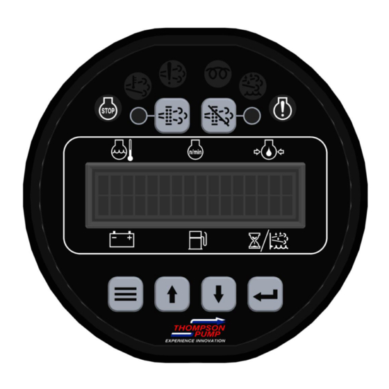
Indicator Lamps Regen Regen Lamp Inhibit Active Engine Engine Lamp Lamp Lamp Fault Alarm Lamp Lamp Active and Stored Engine ECU Codes The panel also provides the ability to check the engine ECU for all ACTIVE and STORED engine ECU codes. These codes can be viewed via the Active Codes and Stored Codes menus. - 8 -... -
Page 9: Control Panel Analog And Digital Inputs
CONTROL PANEL ANALOG AND DIGITAL INPUTS The panel has one analog input and up to one digital input available to monitor other components, senders or signals. These inputs can be used for a number of purposes including alarms and shut downs. -
Page 10: Menu System
MENU SYSTEM To Enter Menu System Hold MENU button and press ENTER button. Menu Navigation Press MENU button to scroll menu options. Press UP arrow button to enter menu. Press DOWN arrow button to reverse. Exit Menu System Hold MENU button and press ENTER button. To Change a Setting Press ENTER button to bring up brackets [ ]. - Page 11 Main Menus Main Menus Sub Menus Emissions Parameters View/Scroll Active Fault Codes Active Engine Fault Codes View/Scroll Active Fault Codes Engine Parameters View ECU Engine Information Viewing Menus (% Load, Torque, Oil Temp, etc.) Engine Identification Engine Model # View Engine Serial # View Module Information Control Unit Part# View...
-
Page 12: Emissions Monitoring
TSC Ramp Rate Selection Throttle Curve Selection Module Configuration Display Units (English, Metric) Hour meter Source (Engine ECU, Internal) Battery Source (J1939, Internal) Battery Volt Trim CAN Configuration Source Address (Default = 44) Others available TSC1 Address (Default = 3) Others available... - Page 13 CONTROLS, INCORPORATED C O N T R O L S Y S T E M S & S O L U T I O N S The panel provides lamp indications, display messages and other emission related information. This information is broadcast from the engine ECU and is captured and displayed by the panel. The panel includes an Emissions Parameters viewing menu that allows the operator to view the following emissions related information.
- Page 14 CONTROLS, INCORPORATED C O N T R O L S Y S T E M S & S O L U T I O N S Regeneration The regeneration process is controlled by the engine ECU. The engine ECU monitors emissions parameters such as soot level and ash level.
- Page 15 CONTROLS, INCORPORATED C O N T R O L S Y S T E M S & S O L U T I O N S DPF Lamp DPF Lamp (Blinking) (Blinking) At the most severe level, the DPF lamp blinks and the red engine alarm lamp illuminates.
- Page 16 CONTROLS, INCORPORATED C O N T R O L S Y S T E M S & S O L U T I O N S Regen Lamp Active Lamp The regeneration active lamp illuminates during the regeneration process. The DFP lamp stays illuminated until the engine ECU determines that a regeneration is no longer required.
Need help?
Do you have a question about the J1939 and is the answer not in the manual?
Questions and answers