
Related Manuals for Relat BM3000

Summary of Contents for Relat BM3000
- Page 1 User Manual BM3000 Battery Monitoring System Copyrights © Shenzhen Relat Electronic Technology CO., LTD. All Rights Reserved...
-
Page 2: Table Of Contents
User Manual Content 1. Product Overview..................................2 1.1. Functions..................................2 1.2. Range of Application..............................2 2. BMS System Description................................3 2.1. General Specification..............................4 2.2. BMS Component List..............................5 2.3. Control Module(BM00MC)............................6 2.4. Battery Sensor(R-Sensor) BM3KRS..........................9 2.5. Current Detector (I-Sensor) BM00IS..........................10 3. -
Page 3: Product Overview
Provide battery management software for measure, record and report, can display the analysis graphs. 1.2. Range of Application BM3000 Battery Monitoring system can monitor the standard of 2V, 6V, 12V battery, battery capacity is up to 3000Ah, battery total voltage can reach 48V,110V,220V, 400V and etc, it meets the requirements of most users. -
Page 4: Bms System Description
User Manual 2. BMS System Description BM3000 Monitoring system using modular level designed, which is easy for the installation and expansion. BM3000 hardware composed with → Control Module, → Current Detector, → Battery Sensor, → Battery Management Software System configuration as below:... -
Page 5: General Specification
User Manual Battery Management Software is installed at laptop or desktop, allows for remote viewing and data management of all connected battery monitoring systems. Report generation, graph and trending curves, detailed alarms can all be viewed on multiples of laptop or desktop on the same network. 2.1. -
Page 6: Bms Component List
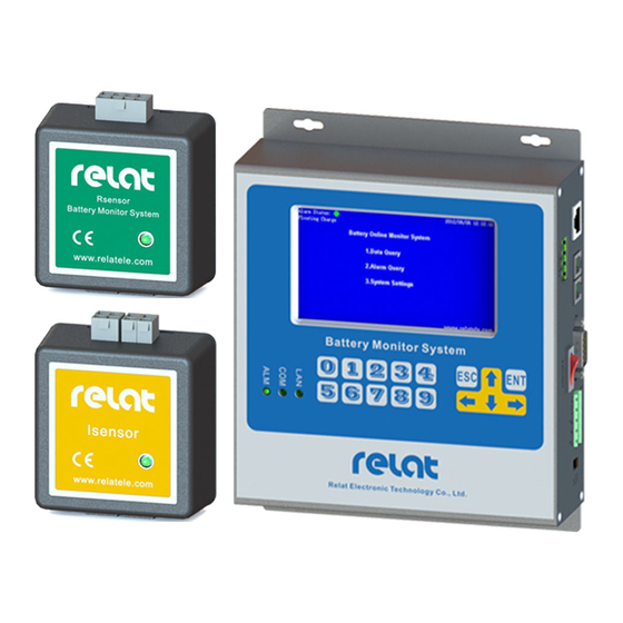
User Manual 2.2. BMS Component List Please check the BMS Component List below, Table 2.BMS Component List Product Picture Product Name Description Control Module Max connected with 254 block BM00MC batteries and 6 battery strings. Battery Sensor One block battery require one BM3KRS R-Sensor Current Detector... -
Page 7: Control Module(Bm00Mc)
User Manual One block battery require 2 PCS Kelvin Washer Kelvin Washer Fixed length of Telephone cable RJ11 Connector with RJ11 connector. 2.3. Control Module(BM00MC) Control Module (BM00MC) is the core component of battery monitoring, allowed to wall mounting. Designed to receive transmitted signals from the Battery Sensor and Current Detector. ... - Page 8 User Manual Dimensional Drawing as below, Interface Description ① ② ③ ④ ⑤ ⑥ LAN : Ethernet interface connect to computer or network switch, allow for web configuration or connecting to SCADA software via Modbus TCP. (Baud rate is 9600) RESET: Long press 5 seconds to reset the device IP address to 192.168.1.100 Loading: loading the firmware RS485: RS485 interface connect with monitoring software, uploading battery data.
- Page 9 User Manual LED Description ① ② ③ ④ ⑤ ⑥ ① RUN: If BM00MC control module is power on, the green light should be on. ②FAULT: Hardware detection indicator, if there’s any fault component, the red light should be on. ③ALARM: Alarm indicator, if there’s any alarms, the red light should be on.
-
Page 10: Battery Sensor(R-Sensor) Bm3Krs
User Manual 2.4. Battery Sensor(R-Sensor) BM3KRS Battery sensor(R-Sensor) BM3KRS can measure the battery cell voltage, temperature and internal resistance, and transmit the measurement to the Control Module for analysis and storage. Table 4. Battery Sensor BM3KRS Specifications Model BM3KRS-LV BM3KRS-HV Cell Voltage 2V/3.7V 6V/12V... -
Page 11: Current Detector (I-Sensor) Bm00Is
User Manual Description, Battery Cable Plug: Place in battery cable and connect to battery positive and negative pole RBUS Port: Place in RBUS cable and connect to neighbouring sensors for communication RBUS Port: Place in RBUS cable and connect to neighbouring sensors for communication Led indicator: Run is Green, Alarm is Red. - Page 12 User Manual Table 5. Current Detector BM00IS Specifications Model IS-100/200/300/400/1000 Current Measurement Range* 0~100/200/300/400/1000A Accuracy ±1% Full Scale Operating Temperature 0-50°C Humidity ≤ 95% Power Supply DC 24/48V Power Consumption < 1.6 W Communication Interface RJ10 Communication Protocol R-bus Dimensions (H x W x D) 60x59x28mm Weight *The current measurement range depend on the current transformer.
-
Page 13: Preparation For Installation
User Manual 3.Preparation for Installation 3.1. Preparation Work Installation drawing and BMS layout should be completed before installation, all anticipating technician should familiar with all the installation procedure, make sure all component mounting position and the wiring methods. All the installation process should follow with the installation guide. 3.2. - Page 14 User Manual Measure battery internal resistance. After MC Internal resistance annual verification. tester Measure the current, and check the UPS status. Current clamp After MC annual verification. Access AC power for installation jobs Electrical outlets Testing and Commission Laptop Diagonal pliers Cutting wire Needle-nose pliers Used to bend, re-position and snip wire...
-
Page 15: Checking The Product Package
Nylon cable tie Tie the cable Cable trunking Cable wiring Label for battery Identify the number to all the battery (Relat Supply) Insulating tape Used to insulate electrical wires/battery terminal Clean Rag Clean battery surface and the battery rack 3.4. -
Page 16: Safety Information
User Manual Step 13, Power on the Control module and inquiry and verify the reading of block voltage and temperature if correct. Step 14, Manual performance An Internal Resistance Test and verify the reading of block impedance if correct. Step 15, Revised the impedance high limit(the impedance reading plus 1.5 times ) Step 16, Save the Impedance Reference. -
Page 17: Installation Guide
User Manual 5. Installation Guide 5.1. Personal Protective Equipment (PPE) requirements The following personal protective equipment shall be available to personnel who perform battery maintenance work: goggles and face shields, acid-resistant gloves, protective aprons, portable or stationary water facilities for rinsing eyes and skin in case of contact with electrolyte, class C fire extinguisher, acid or alkaline neutralizer, and adequately insulated tools. -
Page 18: Step 1: Determine Battery Numbers
User Manual 5.2. Step 1: Determine battery numbers Designate a battery number for each battery in the system. Before connecting the Battery Sensor BM3KRS to the batteries, the batteries should be numbered and labeled correctly by using a label to paste on the surface of the battery where the labels are easy to be seen. -
Page 19: Step 2: Install The Kelvin Washers
User Manual 5.3. Step 2: Install the Kelvin washers Electrical Hazard: A short-circuit can result in injury or death. Do not work alone. Perform a battery disconnection from the UPS system. Use Multimeter measures and confirms there’s no voltage difference between battery and battery rack. 1) Remove the bolt from a battery;... -
Page 20: Step 3: Connect The Battery Cables
User Manual 5.4. Step 3: Connect the battery cables 1) Use an insulated pair of pliers (Important: Do not use your bare hands!) to slide the receptor end of each cable over the tab portion on the washers that you installed on the positive and negative terminals of each battery. -
Page 21: Step 4: Install Battery Sensor Bm3Krs
User Manual 5.5. Step 4: Install battery sensor BM3KRS 1) Find the correct ID of Battery Sensor BM3KRS according to the battery number, then insert the 8 pin connector on battery cable to BM3KRS. 20 / 31... - Page 22 User Manual 2) Place a horizontal reference line to make the sensors look neat. 3) Remove the backing from the adhesive patches on the battery sensor then position and mount it onto the top or side of the battery block (Important: Make sure the surface is clean!). 21 / 31...
-
Page 23: Step 5: Install Current Detector Bm00Is
User Manual 5.6. Step 5: Install Current Detector BM00IS Remove the backing from the adhesive patches on the I-Sensor then position and mount it onto the top or side of the battery block, or on the battery rack (Important: Make sure the surface is clean!). Connect all the cables as below. -
Page 24: Step 6: Connect R-Bus Communication Cable
User Manual Negative Positive Towards Positive, Avoid Negative 5.7. Step 6: Connect R-bus communication cable Connect all R-bus communication cables of battery sensor BM3KRS and BM00IS. 23 / 31... -
Page 25: Step 7: Install Control Module
User Manual 5.8. Step 7: Install Control Module Wall Mount the Control Module or Mounting at the battery rack as below picture. Connect all the cables to the Control Module BM00MC as following. Control Module BM00MC have 2 RBUS Ports, Max. Connect with 508 PCS battery sensors. Each R-BUS port of BM00MC is Max. -
Page 26: Configuration Tool
User Manual 6. Configuration Tool The configuration tool will be more easier for user to revise the system configuration and alarm setting. It’s allowed to connect the configuration tool via serial port Or Ethernet port. Please confirm the serial port is in normal use. If you know the network address and port number of the control module BM00MC, you can also use network cable to remote configuration. -
Page 27: Configuration
User Manual 6.3. Configuration Please unzip the folder and open the configuration file, and double click en-cfg.bat It will go into the configuration page as below picture ① ⑤ ⑥ ③ ② ⑧ ⑨ ④ Pop-up Message bar ⑦ ①Please select the communication port, if use the serial port connection, please select ‘serial port’ and select the relevant serial port, if use the Ethernet port connection, please select ‘Network’, input the IP address and the network port number ②Please click ‘Search’... - Page 28 User Manual ④Click ‘Read’ to get the original setting of the control module ⑤Alarm Setting: Floating V High 2: the high limit of individual battery floating voltage Floating V Low: the low limit of individual battery floating voltage Charge V High: the high limit of individual battery charge voltage Charge V Low:the low limit of individual battery charge voltage Discharge V Low:the low limit of battery discharge voltage IR High:the high limit of internal resistance...
-
Page 29: Alarm Setting List
°C 7.Battery Management Software BM3000 BMS comes complete with Battery Management Software package which allows all battery systems to be monitored 7 x 24 hours via a remote computer. It allows for remote viewing and data management of all connected battery monitoring systems. Report generation, trending analysis, & detailed alarming can all be viewed on a single or multiple PC’s on the same network. -
Page 30: Integrated To The 3Rd Party Software
User Manual 8.Integrated to the 3rd party software 8.1. RS485 Port Control module have RS232/RS485 Port, it support MODBUS RTU Protocol,it’s able to use RS485 port to integrated to the 3rd party software,please find our Modbus Register Map for reference. If connect Using direct connection to COM 1, please configuration the info the same with the red box below. -
Page 31: Ethernet Port
If it’s success to get Modbus TCP connection from control module, please set as below to polling the measurement data. <The End> Shenzhen Relat Electronic Technology Co., Ltd. Add: Suite A602, Huachuangda Centre, Xinhua No.1 Rd, Bao'an District, Shenzhen, 518101 Website:www.relatele.com/en...
Need help?
Do you have a question about the BM3000 and is the answer not in the manual?
Questions and answers