
Related Manuals for Relat BM3000

Summary of Contents for Relat BM3000
- Page 1 User Manual BM3000 Battery Monitoring System Copyrights © Shenzhen Relat Electronic Technology CO., LTD. All Rights Reserved...
-
Page 2: Table Of Contents
User Manual Content 1. Product Overview..................................2 1.1. Functions..................................2 1.2. Range of Application..............................2 2. BMS System Description................................3 2.1. Control Module(CM) BM00CS............................5 2.2. Battery Sensor(R-Sensor) BM3KRS..........................8 2.3. Current Detector (I-Sensor) BM00IS..........................9 3. Preparation for Installation..............................10 3.1. Preparation Work.................................10 3.2. -
Page 3: Product Overview
1.2. Range of Application BM3000 Battery Monitoring system can monitor the standard of 2V, 6V, 12V battery, battery capacity is up to 3000Ah, battery total voltage can reach 48V,110V,220V,400 and various voltage, it meets the requirements of most users. -
Page 4: Bms System Description
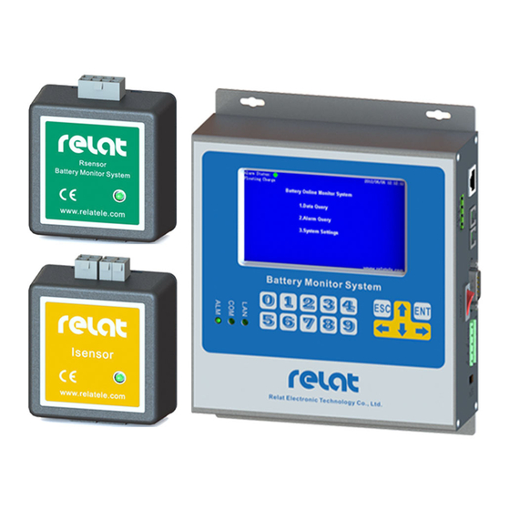
BM3000 Monitoring system using distributed modular designed, which is easy for the installation and expansion. Product system configuration as below: The Relat Battery Monitoring System(BMS) is composed of the control module, current detector and the battery sensor. Please check the BMS Component List below, Table 1. - Page 5 User Manual Battery Sensor One block battery require BM3KRS one R-Sensor Current Detector One string batteries BM00IS require one I-Sensor One string batteries Current Transformer require one current 100A – 1000A transformer MEAN WELL Power Supply 24VDC Accessory of BM00CS Power Input Cable for 24VDC power adapter Battery Cable with...
-
Page 6: Control Module(Cm) Bm00Cs
User Manual 2.1. Control Module(CM) BM00CS Control Module (BM00CS) is the core component of BMS, one Control Module required per UPS and Battery System. Designed to receive transmitted signals from the Battery Sensor and Current Detector. Continuously monitors, analyzes, and stores battery measurements. Equipped with a LCD color display for access to all battery measurements and most BMS settings. - Page 7 User Manual 3D Drawings: Interface Description 24VDC: DC 24V power input and output 24VDC: DC 24V power input and output ON/OFF: Power switch LAN: Ethernet port, connect to computer or network switch R-bus: Connect Battery Sensor BM3KRS and Current Sensor BM00IS. RS232: CM loading interface, to initialize all CM parameters.
- Page 8 User Manual Function Switch: loading the software of control module Normal CM configuration RS232/485: Extensible RS232/485 interface RELAYS: Dry contact output, rated Load: 0.5A @125VAC, 1A@24VDC System On & Status OK – Contact closed. System On & Status Error – Contact open. System Off –...
-
Page 9: Battery Sensor(R-Sensor) Bm3Krs
User Manual 2.2. Battery Sensor(R-Sensor) BM3KRS Battery sensor(R-Sensor) BM3KRS can measure the battery cell voltage, temperature and internal resistance, and transmit the measurement to the Control Module for analysis and storage. Table 3. Battery Sensor BM3KRS Specifications Model BM3KRS-LV BM3KRS-HV Cell Voltage 2V/3.7V 6V/12V... -
Page 10: Current Detector (I-Sensor) Bm00Is
User Manual 2.3. Current Detector (I-Sensor) BM00IS The Current Detector(I-Sensor) BM00IS could be connected to a current transformer to measure the battery string current, and transmit the data transmit the measurement to the Control Module for analysis and storage. To Current Transformer DC 24/48V Power Supply To R-bus Table 4. -
Page 11: Preparation For Installation
User Manual 3.Preparation for Installation 3.1. Preparation Work Installation drawing and BMS layout should be completed before installation, all anticipating technician should familiar with all the installation procedure, make sure all component mounting position and the wiring methods. All the installation process should follow with the installation guide. - Page 12 User Manual Measure battery internal resistance. After MC Internal resistance annual verification. tester Measure the current, and check the UPS status. Current clamp After MC annual verification. Access AC power for installation jobs Electrical outlets Testing and Commission Laptop Diagonal pliers Cutting wire Needle-nose pliers Used to bend, re-position and snip wire...
-
Page 13: Checking The Product Package
Nylon cable tie Tie the cable Cable trunking Cable wiring Label for battery Identify the number to all the battery (Relat Supply) Insulating tape Used to insulate electrical wires/battery terminal Clean Rag Clean battery surface and the battery rack 3.4. -
Page 14: Safety Information
User Manual 4.Safety Information Batteries are potentially dangerous, and proper precautions must be observed in handling and maintenance of batteries and monitoring systems. Maintenance shall be done only by personnel with knowledge of batteries and the monitoring system and trained in the safety precautions involved. Properly insulated tools and adequate personal protective equipment should be used when working with batteries. -
Page 15: Installation Guide
User Manual 5. Installation Guide 5.1. Personal Protective Equipment The following personal protective equipment shall be available to personnel who perform battery maintenance work: goggles and face shields, acid-resistant gloves, protective aprons, portable or stationary water facilities for rinsing eyes and skin in case of contact with electrolyte, class C fire extinguisher, acid or alkaline neutralizer, and adequately insulated tools. -
Page 16: Step 1: Determine Battery Numbers
User Manual 5.2. Step 1: Determine battery numbers Designate a battery number for each battery in the system. Before connecting the Battery Sensor BM3KRS to the batteries, the batteries should be numbered and labeled correctly by using a label to paste on the surface of the battery where the labels are easy to be seen. -
Page 17: Step 2: Install The Kelvin Washers
User Manual 5.3. Step 2: Install the Kelvin washers Electrical Hazard: A short-circuit can result in injury or death. Do not work alone. Perform a battery disconnection from the UPS system. Use Multimeter measures and confirms there’s no voltage difference between battery and battery rack. Remove the bolt from a battery;... -
Page 18: Step 3: Connect The Battery Cables
User Manual 5.4. Step 3: Connect the battery cables (Important: Do not use your bare hands!) Use an insulated pair of pliers to slide the receptor end of each cable over the tab portion on the washers that you installed on the positive and negative terminals of each battery. -
Page 19: Step 4: Install Battery Sensor Bm3Krs
User Manual 5.5. Step 4: Install battery sensor BM3KRS Find the correct ID of Battery Sensor BM3KRS according to the battery number, then insert the 8 pin connector on battery cable to BM3KRS. 18 / 35... - Page 20 User Manual Place a horizontal reference line to make the sensors look neat. Remove the backing from the adhesive patches on the battery sensor then position and mount it onto the top or (Important: Make sure the surface is clean!) side of the battery block 19 / 35...
-
Page 21: Step 5: Install Current Detector Bm00Is
User Manual 5.6. Step 5: Install Current Detector BM00IS Remove the backing from the adhesive patches on the I-Sensor then position and mount it onto the top or side of the (Important: Make sure the surface is clean!) battery block, or on the battery rack Connect all the cables as below. -
Page 22: Step 6: Connect R-Bus Communication Cable
User Manual Make sure the current transformer is in correct direction. Negative Positive Towards Positive, Avoid Negative 5.7. Step 6: Connect R-bus communication cable Connect all R-bus communication cables of battery sensor BM3KRS and BM00IS. 21 / 35... -
Page 23: Step 7: Install Control Module
User Manual 5.8. Step 7: Install Control Module The control module should be mounted at a wall,enclosure or battery rack. Enclosure Mounted at the wall or battery rack. Connect all the cables to the Control Module as below picture: All Control module, battery sensors and the current detectors are daisy chain R-BUS connection from R-Bus Port1 back to R-Bus Port 2 as a closed loop. -
Page 24: Query And Setting
User Manual Till now, all the installations is complete. Check all the connections of battery sensor, I-Sensor and Control Module, to make sure all are correct, especially the positive and negative terminal of batteries and power, before power on them. If required wiring from the floor or the bridge,please check with the user if need to installation of PVC trunking, to ensure safe and neat in the battery room. -
Page 25: Checking All Data If Correct
User Manual MENU TREE From Menu, press Number Key to enter different menu item, to query data or alarm. For example, to get “Single battery block data”, main menu press Key ”1” press Key “2”, then all single battery online data will be shown on the LCD screen, each page will show 10 pcs battery, press Arrow Key up or down to turn page. -
Page 26: Checking Alarm
User Manual 6.2. Checking Alarm It’s able to query the detailed alarm info from Control Module(BM00CS) From main interface, press ‘2’ to enter ‘2.Alarm’ menu, and press ‘1’ to enter “1. Live Alarm”menu, please check what alarm is happening now. From main interface, press ‘2’... -
Page 27: Advanced Setting
User Manual 7.Advanced Setting 7.1. Alarm Setting From main interface, press 4 to enter ‘4.System’ menu, press 2 to enter ‘2.Alarm’ menu. ← left key is delete the valve, ↓ down key is switch to next one alarm setting 7.2. Impedance Setting ♦... - Page 28 User Manual 1. When enter the ‘1. Clear’ menu, the Daily Data, Yearly data or history alarm can be clear away. Before clear, please confirm that these data if available for you. 2. When enter ‘2. config ’ menu, it is able to configure the system info. Modbus ID: If connected with multiple sets of control module, the modbus ID of each control module cannot be repeated, it requires to modify the Modbus ID from here.
- Page 29 User Manual 3. When enter ‘3. Impedance Test Date’ menu, the internal resistance can be automatically measure from daily, weekly or monthly, please select the three mode, input the number in the input box. Input the time hour and min to measure impedance.
-
Page 30: System Configuration
User Manual 8. System Configuration Connect Control Module BM00CS to computer through RS232 interface. Kindly check the toggle switch at the side of control module.Make sure the toggle switch is in “CFG” position. Restart CM.(Power off and Power on) Open software “CM CONFIG V2.0.1.exe”. Take the following steps to configure all settings. - Page 31 User Manual Cell C V Max: the maximum of battery charge voltage Cell C V Min: the minimum of battery charge voltage Cell Temp Max: the maximum battery temperature Cell Delta IR: the battery Internal Resistance change rate Cell Rated IR Max: the rated maximum battery internal resistance Cell No.: battery number, when it’s “000”, all battery IR Ref will be changed IR ref Value: battery internal resistance reference Step 4: Compare all the settings between PC and CM, the different setting items will be shown as red color in...
-
Page 32: Alarm Setting Form
User Manual Example of configuration: Battery: 12V 100Ah 2 Stings, each string 20 blocks battery 9.Alarm Setting Form Block Voltage 12 V Alarm Type Discharge Voltage Low Limit 1850 mv 5550 mv 11100 mv Float 1 Voltage High Limit 2350 mv 7050 mv 14100 mv Float 2 Voltage High Limit... -
Page 33: Integrated To The 3Rd Party Software
User Manual Charge I (Current) H (High) Limit: Battery Nominal Capacity 0.25C multiply string/bank number. (C stand for battery capacity) Example. battery setup is 1 set of UPS x Bank x 32 Block 12V Ah battery, 0.25 x 100 Ah x 2 Bank=50 A Bank V (Voltage) H (High) Limit: Charge V H limit multiply battery quantity of each bank Example. -
Page 34: Ethernet Port
User Manual 10.2. Ethernet Port Control module have Ethernet Port, it support MODBUS TCP/IP Protocol,it’s able to use Ethernet port to integrated to the 3 party software,please find our Modbus Register Map for reference. If connect Using direct connection to Ethernet port, please select ‘Remote Modbus TCP Server’ from the Modscan tool. - Page 35 User Manual Shenzhen Relat Electronic Technology Co., Ltd. Add: Suite A602, Huachuangda Centre, Xinhua No.1 Rd, Bao'an District, Shenzhen, 518101 Tel: +86-755- 2956 3743 Fax: +86-755- 2976 9341 34 / 35...
Need help?
Do you have a question about the BM3000 and is the answer not in the manual?
Questions and answers