Table of Contents
Advertisement
Quick Links
ASSEMBLY INSTRUCTIONS
S CHAPTER
1
•
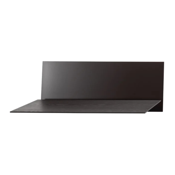
The mounting rail is the central
suspension point for all CHAPTER
elements.
•
Align the rail horizontally at the desired
wall position and mark drilling points in
the center of the slotted holes, this allows
a horizontal shift of +/- 3mm.
•
The rail itself can be used as a drilling
template, a spirit level can be placed
well on the upper surface for accurate
leveling.
•
Dowels and wall screws are included.
2
•
Now slide the tray over the rail from below
and secure it through the bore holes with
two screws at each side.
3
•
The back panel is now slid over the side
walls of the tray with its slots facing down-
wards and then put back against the rail.
•
Make sure that the side with the counter-
sunk drill holes is facing forward.
Advertisement
Table of Contents

Related Manuals for LOEHR S1 CHAPTER

Summary of Contents for LOEHR S1 CHAPTER
- Page 1 ASSEMBLY INSTRUCTIONS S CHAPTER • The mounting rail is the central suspension point for all CHAPTER elements. • Align the rail horizontally at the desired wall position and mark drilling points in the center of the slotted holes, this allows a horizontal shift of +/- 3mm.
- Page 2 ASSEMBLY INSTRUCTIONS S CHAPTER • The two screw points now connect the back panel to the rail. • Ensure a tight connection, the rear panel has approx. 10mm clearance to the wall at the top edge when correctly installed. • For transportation, the divider and the table top are shipped with connected hinges.
- Page 3 ASSEMBLY INSTRUCTIONS S CHAPTER • Now insert the divider into the tray. Two screw points on both sides determine the position. • Secure the divider firmly with four of the enclosed screws.
- Page 4 CHAPTER is now usable. ENJOY! ATTENTION: The nature and strength of the wall, as well as the professional, safe installation, are decisive for the load capacity of the desk. The specified values apply only if these factors are given. LOEHR.CO 02-2022 SUPPORT LOEHR.CO...
Need help?
Do you have a question about the S1 CHAPTER and is the answer not in the manual?
Questions and answers