Table of Contents
Advertisement
Quick Links
Advertisement
Table of Contents

Related Manuals for OCSTAT E3RF


Summary of Contents for OCSTAT E3RF
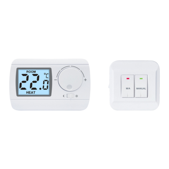
- Page 1 Wireless RF Room Thermostat Operating Instructions English Language...
- Page 2 GENERAL DESCRIPTION OF THE THERMOSTAT This type switched-mode room thermostat is suitable to regulate the overwhelming majority of boilers available in Europe. It can easily be connected to any gas boiler or air conditioning device that has a double wire connector for a room thermostat, regardless of whether it has a 24 V or 230 V control circuit.
- Page 3 The switching sensitivity of the thermostat is ± 0.1°C (± 0.2°C). This means the difference between the adjusted temperature and the actual temperature The information shown on the liquid measured during the crystal display of the thermostat switching process. includes the following: For example, if Room the factory default...
- Page 4 1. LOCATION OF THE DEVICE It is reasonable to locate it in a room used regularly or for many hours per day so that it is in the direction of natural ventilation in the room but protected from drought or extreme heat (e.g. direct sunlight, refrigerator, chimney, etc).
-
Page 5: Installation Of The Thermostat
2. INSTALLATION OF THE THERMOSTAT Vertical angle: • To install the thermostat, Remove the 30 - 45° rear panel of the thermostat from the front panel using a screwdriver as shown. Latch • With the help of the screws provided and some tools fasten the rear panel of the device to the wall. - Page 6 Attention! The device must be installed and connected by a qualied professional. Always follow the manufacturer’s instructions when connecting the thermostat to any heating or cooling appliance. The voltage appearing at terminal No. 1, No. 2 or No. 3 depends only on the system being controlled, therefore the dimensions of the wire are determined by the type of the...
- Page 7 3. PUTTING THE THERMOSTAT INTO OPERATION To put the thermostat into operation, Remove the rear panel of the thermostat from the front panel as shown The battery compartment is on the inside of the front panel of the case. Insert 2 AA alkaline batteries (TYPE LR6) into the battery compartment as shown.
- Page 8 4. Coding switch selection After removing the rear panel of the device, desired Settings can be obtained by changing the coded switch on the PCB board. The heating mode The Cooling mode HEAT COOL Temperature sensitivity Temperature sensitivity +0.2 ℃ +0.1℃ ℃...
-
Page 9: Setting The Desired Temperature
5. SETTING THE DESIRED TEMPERATURE When the factory default temperature is set to 20°C and the factory default temperature is set to 20°C, the temperature of the thermostat switch on the connected heating device is lower than 19.8°C (connecting terminals 1 and 2) and higher than 20.2°C (disconnected terminals 1 and 2) under the switch sensitivity (±0.2°C). - Page 10 6. Heating Mode According to the change in room temperature and temperature setting, the device controls (switches on or off) the boiler or any other heating equipment connected to the appliance. When activated, the normally open contact pairs, i.e. No. 1 (NO) and No. 2 (COM), of the relay of the device clamp shut, and, as a consequence, the appliance connected to the thermostat is switched on.
- Page 11 7. Cooling mode According to changes in room temperature and temperature setting, the equipment control (switch) is connected to the refrigeration equipment. When activated, the normally open contact pairs of the device clamp relay, i.e., No. 1 and No. 2 (COM), are closed, so that the appliance connected to the thermostat is on.
-
Page 12: Battery Replacement
9. BATTERY REPLA CEMENT The average lifetime of the batteries is 1 year. The “ ” It is displayed on the LCD,Replace the batteries whenever the “ ” icon indicating low battery voltage appears on the display . After battery replacement, the desired temperature should be adjusted again, because during the battery replacement the thermostat is reset to factory default settings. -
Page 13: Learn Code
10. Receiver Operation (By press MANUAL to switch the receiver operation mode) 1.Manual mode: Press MANUAL once, the green light will be on (Manual mode), press M/A can control the Relay ON/OFF (ON: red lights on, OFF: red lights off). 2.AUTO mode: Press MANUAL again, the green light will be off (Auto mode), the ON/OFF will be controlled by the transmitter. - Page 14 12. ON/OFF button on the receiver O: OFF When there is no need to use the thermostat for some seasons, the users can just trun OFF (by the left side of the receiver) the power of the receiver and does not need to move off the front case; |: ON The receiver is normal operating.
-
Page 15: Technical Data
TECHNICAL D ATA — switchable voltage: 24 V AC / DC,…230 V AC; 50 Hz — switchable current: 6 A (2 A inductive load) — temperaturemeasurementrange: 0 to 40°C (in 0. 1°C increments) — adjustable temperature range: 5 to 35°C (in 0.5°C increments) —... - Page 16 This type thermostat complies with the requirements of EU standards. Radio Equipment Directive 2014/53/EU RoHS Directive 2011/65/EU...
Need help?
Do you have a question about the E3RF and is the answer not in the manual?
Questions and answers