Advertisement
Quick Links
Advertisement

Related Manuals for babcopark Starke 2127

Summary of Contents for babcopark Starke 2127
- Page 1 User Manual for Pit Lift...
- Page 2 Safety Instructions Overview of Parking Lift Package Installation Hydraulic & Electric Operation Surface Cleaning & Protection Maintenance & Servicing Warranty Policy Certificate...
- Page 3 The Pit Lift is designed for cars parking under the stated maximum weight, any other usage is to be considered improper, thus highly forbidden. Babcopark will not be responsible for any damage or injury resul�ng from neglect or failure of carrying out the requirements in this manual.
- Page 4 Chapter 1 Safety Instructions 1.3.11 If the parking li� is to be le� unused for a long period of time, it’s recommended to: 1.3.11.1 Turn off the power switch on the control box and main switch of the power supply 1.3.11.2 Empty the oil tank and dispose of unused oil properly according to local environmental laws and regula�ons.
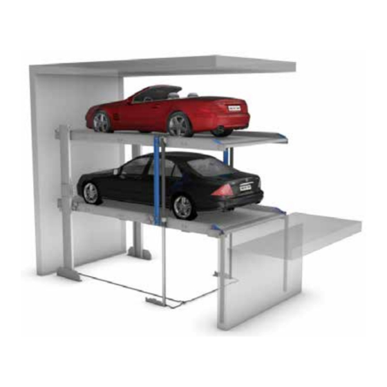
- Page 5 Pit Lift Overview 2 Overview of Parking Lift 2.1 Product Introduction The Pit Lift is the latest version of two post pit parking li�s. A pit two post parking li� mainly consists of two posts, two carriages, two cylinders, one control box, one opera�on panel, one power unit and two pla�orms covered by wave plates.
- Page 6 Pit Lift Overview Dimensions of standard models 5000 5300 (3) Pit Lift 5000 5300 (4) Pit Lift...
- Page 7 The lowering speed of an empty pla�orm is considerably lower than a loaded one. Babcopark reserves the right to construc�on or model modifica�ons and/or altera�ons. Furthermore, the right to any subsequent part modifica�on and/or varia�ons and amendments in procedures and standards due to technical and engineering progresses in the art or due to environmental regula�on changes, are also hereby...
- Page 8 Pit Lift Overview Protection against corrosion Maintenance work has to be carried out regularly according to Surface Cleaning and Protec�on men�oned in chapter 8 of this manual. Clean up galvanized parts and pla�orms of dirt and road salt as well as other pollutants (corrosion danger)! Fire safety Each and every fire safety requirement and all possible mandatory item(s) and equipment(s) (fire ex�nguishing systems and fire alarm systems, etc.) are to be provided by the customer.
- Page 9 Keep obstacles away from install area. 4.2.3 Founda�on construc�on is to be carried out in accordance with the founda�on requirements in this manual and local regula�ons. Contact Babcopark or local Babcopark partner before construc�on work if customized dimensions or special project condi�on exist. 4.2.4 Founda�on pit with wrong dimensions, poor construc�on, insufficient concrete thickness or absence of...
- Page 10 Pit Lift Installation 4.4.5 Recommended drainage channels: 4.4.5.1 100 x 20 mm, with a 500 x 500 x 200 mm drainage pit 4.4.5.2 In case of installa�on of a sump pump, it is necessary to comply with the drainage pit dimensions specified by the pump manufacturer 4.4.6 Founda�on diagram...
- Page 11 Pit Lift Installation Pit center line 4900 2450 2450 4300 Entrance / Exit Sec�on A-A Ra�o 1 : 30 Pit Lift Double Platform (6) Founda�on diagram...
- Page 12 Pit Lift Installation Assembly 4.5.1 Draw pit center line then other dimension lines in founda�on pit in accordance with below diagram. Cylinder post bracket Pit center line Oil tube Mechanical locking tube 3530 5018 (7) Installa�on layout 4.5.2 Two mechanical locking tubes are to be fixed symmetrically onto front wall by anchor bolts as shown in above diagram.
- Page 13 Pit Lift Installation 4.5.3 The le� post and two cylinder brackets are to be fixed by anchor bolts onto floor slab at posi�ons shown in above diagram. Holes for fixing anchor bolts are to be drilled with 200mm depth by 18mm percussion bit. (9) Fixing le�...
- Page 14 Pit Lift Installation 4.5.5 Three cushion blocks are to be fixed under a le� side beam by hexagon socket countersunk head screw M12*50, flat washer, spring washer and screw nut. Then fix this le� side beam onto lower part of le� carriage by hexagon screw M20*55 at upper part and hexagon screw M20*110 at lower part.
- Page 15 Pit Lift Installation 4.5.7 Fix three connec�on rods by hexagon bolts M14*40, flat washer, spring washer and screw nut with le� and right side beam, and back board by hexagon bolts 16*55, flat washer, spring washer and screw nut in the back of side beams shown as below.
- Page 16 Pit Lift Installation ① ① ② ② Hexagon screw M16*40 with flat ② ① washer, spring washer and screw nut ③ Hexagon screw M16*110 with flat ② washer, spring washer and screw nut Hexagon socket countersunk head ② ③ screw M14*35 (15) Fixing li�ing base 4.5.9 Fix cylinder moun�ng base onto another pair of le�...
- Page 17 Pit Lift Installation 4.5.10 Fix the pair of le� and right side beams with the cylinder moun�ng base onto the upper part of le� and right carriage by the same method of fixing lower side beams. Then both sides of lower side beams and upper side beams are to be connected with connec�on supports by hexagon socket head bolt M24*45, flat washer and spring washer.
- Page 18 Pit Lift Installation 4.5.11 Fix three connec�on rods and back board with upper side beams by same method as lower side beams. (18) Connec�on rods and back board of upper pla�orm 4.5.12 Erect two cylinders on cylinder brackets at two sides with piston facing down. Piston rod is to be extended by compressed air to make cylinder tube end fixed with cylinder moun�ng bases of upper side beams by hexagon bolt M16*35, flat washer and spring washer.
- Page 19 Pit Lift Installation 4.5.13 Chain loosen detec�on mechanism, consis�ng of limit switch, bent plate, pressure spring, threading sleeve, rod and screw nut, is to be assembled onto li�ing plates of le� and right post. ① ① ② ③ ④ ④ ④...
- Page 20 Pit Lift Installation 4.5.14 A piece of chain and wire rope cable is to be assembled at each side of the parking li�, with one end fixed on cylinder bracket, the other end fixed on li�ing plate of each post and going through the two chain wheels and rope sheaves on middle and rear part of le�...
- Page 21 The long oil tube is to be connected to valve block and hydraulic pump in accordance with hydraulic piping diagram provided by Babcopark based on specific project requirements. Hydraulic piping may be different for different project, please contact Babcopark or localBabcopark partner for detailed solu�on.
- Page 22 Pit Lift Installation 4.5.17 Power pack is to be placed at exact posi�on in accordance with project layout, and connected with switching cabinet. 4.5.18 Fill the power pack with sufficient hydraulic oil of quan�ty according to specific order. Note: In normal temperature, hydraulic oil L-HV 46# is recommend, and 32# for low temperature. Viscosity of hydraulic oil should be 15 –...
- Page 23 Pit Lift Installation 4.5.23 Fix all the anchor bolts of right post once the whole structure works well. (25) Anchor bolts of right post 4.5.24 Assemble mechanical an�-falling locks to both sides of the front end of lower pla�orm. (26) Mechanical an�-falling lock...
- Page 24 Pit Lift Installation Electromagnet Ar�culated bearing Locking rod Locking block ① ① ② ③ ④ Cross recessed pan head screw ① M4*14 Cross recessed pan head screw ② M4*35 Hexagon socket head bolt ③ M10*30 Hexagon head bolt ④ M8*80 (27) Mechanical an�-falling lock...
- Page 25 Pit Lift Installation 4.5.25 Connect two electromagnets to the switching cabinet. Two wires from each electromagnet are to be laid separately in le� and right side beam, and connected at the rear end of the le� side beam to the spring wire. The other end of spring wire is to be connected to wire from switching cabinet, and fixed by rubber sleeve steel cable clamp on appropriate posi�on on concrete column or rear wall, where it is closed to the lower pla�orm and at half of li�ing height above bo�om of founda�on pit.
- Page 26 Pit Lift Installation 4.5.27 Top retaining brackets on both le� and right post are to be fixed by anchor bolts to designated posi�ons in accordance with project layout and local regula�ons. (30) Fixing top retaining brackets 4.5.28 Top limit switch is to be mounted to appropriate posi�on based on pit depth, ceiling height and other project condi�ons.
- Page 27 Pit Lift Installation 4.5.29 Connect limit switches for chain loosen detec�on and top limit switch to switching cabinet. ① ③ ② ② ③ ① Wiring of top limit switch Wiring of limit switch for chain ② detec�on ③ Line pipe (32) Limit switches wiring route...
- Page 28 Pit Lift Installation 4.5.30 Waving plates and ramps are to be assembled to side beams of both pla�orms with all bolts and nuts fastened. (33) Assembly of waving plates and ramps 4.5.31 Place a rubber wheel stopper onto each pla�orm without being fixed by a bolt. Posi�on of placement can be adjusted according to different vehicle sizes.
- Page 29 Pit Lift Installation Platform assembly of Pit Lift 4.6.1 Layout chalk lines for pit center line and then other dimension lines in founda�on pit in accordance with below diagram. 4654 Mechanical Lock 4852 Cylinder bracket POST 4807 (35) Installa�on layout (double unit)
- Page 30 Pit Lift Installation 4.6.2 Connect rear beam with le� and right side beam. ① ① Hexagon bolt M16*55 with flat washer, spring Hexagon socket flat round head bolt M16*35 ① ① washer and screw nut with flat washer and spring washer (36) Connec�on of rear beam and side beams...
- Page 31 Pit Lift Installation 4.6.3 Connect middle beam to rear beam ① ① Hexagon socket flat round ① head bolt M16*35 with flat washer and spring washer (37) Connec�on of middle beam and rear beam...
- Page 32 Pit Lift Installation 4.6.4 Install balance sha� with middle and side beams. (38) Installa�on of balance sha� 4.6.4.1 Components of balance sha� ② ① ② ③ ④ ⑤ ④ ① Spacer A ④ End sha� ② ⑤ Spacer B Connec�on sha� ③...
- Page 33 Pit Lift Installation 4.6.4.2 Place a spacer A and two spacer B underneath middle beam, and make connec�on sha� go through them, then fixed by block. (40) Underneath of middle beam...
- Page 34 Pit Lift Installation 4.6.4.3 Connect connec�on sha� with two end sha�s. The other end of end sha� assembled with chain wheel on side beam. ① ② Hexagon bolt M16*80 with flat washer, spring washer and ① screw nut Hexagon bolt full thread M14*60 with flat washer and ②...
- Page 35 Pit Lift Installation 4.6.6 Assemble spacer bushing, key, chain wheel, catch and screw bolt in sequence to li�ing bases of le� and right side beam. Then fix all the screw bolts on li�ing bases. 4.6.7 Connect another le� and right side beam to upper part of carriages, the upper and lower side beams of both sides are to be fixed by connec�on support.
- Page 36 Pit Lift Installation 4.6.9 Erect two cylinders on the cylinder brackets at two sides with piston facing down. Piston rod is to be extended by compressed air to make cylinder tube end fixed with cylinder moun�ng bases of upper side beams by hexagon bolt M16*35, flat washer and spring washer.
- Page 37 Pit Lift Installation 4.6.10 Install two connec�on beams in the middle of each pla�orm, then covered by two middle cover plates. Do not fasten the nuts at this time, to provide enough space for waving plates assembly. (46) Installa�on of connec�on beams (47) Installa�on of middle cover plates...
- Page 38 Pit Lift Installation 4.6.11 Install ramp at the front of each pla�orm. Do not fasten the nuts at the moment, to provide enough space for waving plates assembly. ① Hexagon socket flat round head bolt M16*60 with flat washer, ① spring washer and screw nut (48) Installa�on of ramp 4.6.12 Waving plates are to be assembled on each pla�orm.
- Page 39 Pit Lift Installation 4.6.13 All bolts shall be fastened a�er assembly of waving plates finishes. (50) En�re pla�orms...
- Page 40 Hydraulic & Electrical Hydraulic & Electrical 5 Hydraulic schematic diagram (51) Hydraulic schema�c diagram (single unit) Filler Cylinder Moter Solenoid valve Gear pump Thro�le valve Relief valve Oil tank One-way valve Solenoid vslve Note: UP: Motor is working, solenoid valve YV1 is opened and buzzer is making a sound un�l top limit switch struck by carriage. DOWN: Solenoid valve YV2 and YV3 are both opened, and buzzer is making a sound.
- Page 41 Hydraulic & Electrical (52) Hydraulic schema�c diagram (triple unit) Filler Cylinder Moter Solenoid valve Gear pump Thro�le valve Relief valve Oil tank One-way valve Solenoid vslve Note: UP: Motor is working, solenoid valve YV1 is opened and buzzer is making a sound un�l top limit switch struck by carriage. DOWN: Solenoid valve YV2 and YV3 are both opened, and buzzer is making a sound.
- Page 42 Hydraulic & Electrical Hydraulic piping diagram The component numbers are referred to Figure 54 & 55. #8 & #9 of the final Valve Block must be plugged. ⑤ ④ ⑧ ⑨ ⑤ ④ ⑧ ⑨ ⑤ ④ (53) Hydraulic piping diagram...
- Page 43 Hydraulic & Electrical ② ① ③ ④ ⑨ ① Plug ⑤ ② To cylnders ③ Speed governor ⑧ ④ Oil outlet ⑦ Oil inlet ⑤ ⑥ Solenoid for Up(YV1) ⑥ Solenoid for Down (YV2) ⑦ Oil outlet ⑧ ⑨ Oil inlet (54) Components &...
- Page 44 Oil tank Thro�le valve (56) Hydraulic valves on power pack Cau�on: Serious malfunc�on, even human injury can occur if not properly followed. Contact Babcopark or local Babcopark partner for permission and technical support before adjustment. 5.3.1 Se�ng pressure adjustment of pressure relief valve 5.3.1.1 Unscrew cap from pressure relief valve, and rotate inner adjus�ng screw to reset pressure.
- Page 45 Hydraulic & Electrical Electrical diagram (57) Electrical diagram Note: The two limit switches for chain loosen detec�on are connected in series and NC (Normal Close).
- Page 46 Hydraulic & Electrical Wiring diagram (58) Wiring diagram...
- Page 47 6.2.2 The parking brake shall be turned on a�er vehicle on the targeted posi�on to avoid any accidental movement. 6.3.3 Over loading is not allowed. the rated capacity of Starke 2127/2227 is 2700kg and Starke 2121/2221 is 2100kg.
- Page 48 Operation 6.2.4 Open the car door carefully to avoid any collision. Pay a�en�on to the waving plates and side beams in case any falling down of person. 6.2.5 Make sure the car sizes and weight is in allowance range of this parking li� before leaving. Operation 6.3.1 An inspec�on of equipment is necessary before opera�on and to make sure lift is in good working order.
- Page 49 7.1.3.2 Posts, post bases and post mounts are to be cleaned of dirt deposits. Recommended frequency: At least 2 x yearly 7.1.3.3 Dry clean the pits, swept-clean. Cau�on: Risk to life and limb! Before cleaning the ground/pits it is essen�al to request your local Babcopark partner to secure the parking li�s. 7.1.4 Disposal For the proper disposal the local authori�es, such as municipal authori�es, environmental protec�on office or...
- Page 50 Surface Cleaning & Maintenance Recommended frequency: At least 2 x yearly. Check during basic cleaning and treat if necessary 7.2.4 Disposal The materials we have named are to be disposed off in accordance with the respec�ve manufacturer’s recommenda�ons. For proper disposal the local authori�es, such as municipal authori�es, environmental protec�on office or trade supervisory council, are to be informed –...
- Page 51 Surface Cleaning & Maintenance 8.1.13 An electromagnet with noise shall be replaced ASAP. 8.1.14 Any broken safeguards, warning signs, safety informa�on, markings and ligh�ng shall be replaced in �me. Servicing 8.2.1 If the pla�orm �lts fore-and-a� when li�ing, first check if vehicle is parked correctly; second check the perpendicularity of post.
- Page 52 Surface Cleaning & Maintenance 8.3.3 Trouble shoo�ng of power pack Trouble Possible causes Solutions Re-connect wires from main power supply The rota�on of motor is in wrong to motor to make motor rotate with direc�on due to incorrect motor wiring correct direc�on Not enough hydraulic oil in oil tank Hydraulic oil to be replenished into oil tank...
- Page 53 Surface Cleaning & Maintenance Valve element of one-way valve is blocked One-way valve to be cleaned or replaced Pressure cannot Valve element of solenoid valve is blocked Solenoid valve to be cleaned or replaced be maintained after platform Fi�ng of outlet pipe is not fastened or Fasten fi�ng of outlet pipe, or replace lifted up sealing is broken...
- Page 54 Surface Cleaning & Maintenance Maintenance and servicing of cylinder Only trained and qualified staff is allowed to do inspec�on, maintenance and service work of cylinder. 8.4.1 Inspec�on of cylinder Before installa�on and usage of cylinder: 8.4.1.1 Check if the cylinder specifica�ons, such as bore diameter, rod diameter, stroke length, etc. match the model of purchased parking li�.
- Page 55 Surface Cleaning & Maintenance Overlarge cushion clearance Reduce cushion clearance One-way valve/thro�le valve failure in One-way valve/thro�le valve to be repaired Pressure shock cushion device Overlarge pressure in cushion chamber due Diameter and length of cushion chamber to undersized volume to be increased Oversize or undersize fit clearance Repair or replace part with wrong size and...
- Page 56 Surface Cleaning & Maintenance Inspection of hydraulic oil Hydraulic oil, as transmission medium in hydraulic transmission system, makes mechanism and parts in hydraulic system lubricated, cooled and rust-proof. The pressure, temperature and flow speed of hydraulic transmission system changes a lot in large ranges, so the different quali�es of hydraulic oil have direct effect upon working performance of hydraulic system.
- Page 57 Babcopark shall repair or replace at their discretion, the defected parts during the warranty period which proved upon inspec�on to be defec�ve. Babcopark will NOT be responsible for any costs other than the value of the defected parts and the delivery cost of the parts.
Need help?
Do you have a question about the Starke 2127 and is the answer not in the manual?
Questions and answers