Table of Contents
Advertisement
Quick Links
Advertisement
Table of Contents
Troubleshooting

Related Manuals for Milvus Robotics SEIT 500


Summary of Contents for Milvus Robotics SEIT 500
- Page 1 User Manual for SEIT 500 Autonomous Mobile Robot...
-
Page 2: Table Of Contents
User Manual for SEIT 500 Table of Contents Introduction ............................3 1.1. Warning Notices in This Document ....................3 1.2. Symbols ............................4 1.3. Definitions ............................. 4 Safety ..............................5 2.1. General Hazards ..........................5 2.2. Intended Use ..........................6 2.3. -
Page 3: Introduction
If you have any questions after reading the manual, please contact Milvus Robotics. 1.1. Warning Notices in This Document The warning notices refer to risks which may arise while using SEIT 500. They are available in four danger level identified by the signal word: Table 1.1: Signal words and their meaning... -
Page 4: Symbols
SEIT 500 – This is the model name. Attachments – Any passive or dynamic device attached to and possibly powered by SEIT 500. This could be as simple as a cart for carrying objects such as factory parts or as complicated as a robotic arm that picks up and manipulates factory parts. -
Page 5: Safety
The following list informs you about the various types of danger or damage that may occur while working with SEIT 500. Safety Devices Perform any maintenance and repair work on SEIT 500 only in de-energized state and ensure that it cannot be started accidentally. -
Page 6: Intended Use
SEIT 500-ready goods such as small packages, cartons, boxes or different pallet sizes up to 500 kg. SEIT 500 is dimensioned only for a certain field of use (see Technical Data, page 18) and may not be operated outside of these specific limits. - Page 7 The following target groups are addressed in these operating instructions: Operators Operators have been instructed in the operation and cleaning of SEIT 500 and follow the safety guidelines. Service Personnel The service personnel feature a technical training and performs the maintenance and repair tasks.
-
Page 8: Operating Modes
User Manual for SEIT 500 2.4. Operating Modes Normal Mode; the AMR is set up at the customer into a complete system and operated as part of the system. Special Mode; special operation refers to all operating modes which are required to guarantee and maintain regular operation. -
Page 9: Environment
Milvus does not intend SEIT 500 for use in uncontrolled areas without risk analysis. For example, in areas open to general public access. Use of SEIT 500 in such areas requires deployment of additional safety measures. -
Page 10: Battery Safety
2.6. Battery Safety CAUTION Battery Damage Risk SEIT 500 is shipped when the Li-ion batteries’ state of charge is 50%. This state of charge supplies 24 VDC nominal voltage. SEIT 500 must be charged in 45 days after the delivery. -
Page 11: Product Identification
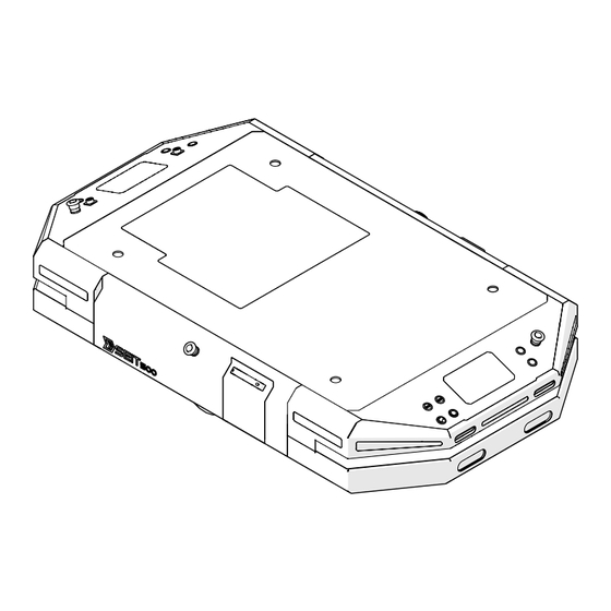
User Manual for SEIT 500 3. Product identification 3.1. Product Overview 3.1.1. SEIT 500 Figure 3.1: Top view of SEIT 500 User Buttons Emergency Stop Buttons Aux I/O Connector USB Ports 24 VDC Aux Power Connector Start/Stop Button Brake Release Buttons On/Off Switch User Buttons –... - Page 12 Lifting Holes Battery Access Lids Lifting Holes – M10 lifting holes for fixation of top module, e.g. RC800 conveyor, and to lift SEIT 500. (See “Applications” for dimensions of the holes, Page. 54) Battery Access Lids – to access battery of SEIT 500.
- Page 13 User Manual for SEIT 500 Figure 3.3: Side view of SEIT 500 Navigation and Safety Lasers (category 3 PL d in accordance with ISO 13849-1) 13 | P a g e Version 2.3 (05/2021) EN...
- Page 14 Led Indicators Depth Cameras Charging Pads Led Indicators – letting the surround know which operation is executed by SEIT 500. Charging Pads – to charge SEIT 500 via charging station. Depth Cameras – detect objects in front of the robot.
- Page 15 User Manual for SEIT 500 3.1.2. SEIT 500 Manual Remote Controller Led indicator Speed decrease Speed increase Activate / Deactivate Manuel (Pendant) control Standart control mode is X Move / Rotate with analogs 2 x AA batteries USB receiver Figure 3.5: Manual remote controller...
- Page 16 User Manual for SEIT 500 3.1.3. AUX I/O Figure 3.6: Contact Arrangement (When viewed from robot connector side) IN1 (Safety Input) TX (RS232) GND (RS232 GND) 24V+ 24V- IN5 (AUX Emergency) RX (RS232) AUX connector supports low current/power devices, and it has 5 inputs and 2 outputs.
- Page 17 User Manual for SEIT 500 3.1.4. AUX Power Figure 3.8: Contact Arrangement (When viewed from connector side) When an emergency or a protective stop 24V+ (Max 15A, Continuous) situation occurs, the power is shut down. It is controlled by a Safety PLC and a contactor.
-
Page 18: Technical Data
User Manual for SEIT 500 3.2. Technical Data SEIT 500 Payload 500 kg Application specific – on top loading, Load Type cart towing, conveyor – chain, roller, lift deck Brake Electric, fail safe Approx. Weight 180 kg (Unloaded) Gradeability 8% - fully loaded... -
Page 19: Transport And Storage
User Manual for SEIT 500 4. Transport and Storage 4.1. Transport SEIT 500 arrives in a wooden box secured by draw letches to a pallet. Use only the pallet, and a rated lifting device to move the shipment. WARNING Risk of injury during transport Fix SEIT 500 securely and slip-proof for the transport. -
Page 20: Storage
Check SEIT 500 stability. If SEIT 500 is not immediately placed in operation, store it at a location protected against humidity and dust or cover SEIT 500 with something that protects it from such conditions. 20 | P a g e... -
Page 21: Getting Started Guide
5.1.1. Box Content • Dimensions; 2200 x 1070 x 654 mm (LxWxH) • Weight; 250 kg (without attachment) Figure 5.1: Box, containing SEIT 500 and its equipments 21 | P a g e Version 2.3 (05/2021) EN... - Page 22 User Manual for SEIT 500 5.1.2. Unpacking Steps Figure 5.2: Exploded view of the box MR AutoC – 500 SEIT 500 Stop Board Protective Wall Pallet Protective Foam Ratchet Strap Ramp 22 | P a g e Version 2.3 (05/2021) EN...
- Page 23 User Manual for SEIT 500 ➢ Remove the ramp and place it as in the Figure 5.3 Figure 5.3: Ramp placement 23 | P a g e Version 2.3 (05/2021) EN...
- Page 24 User Manual for SEIT 500 ➢ Remove the protective wall, protective foam and charging station box. Figure 5.4: Unboxed view 24 | P a g e Version 2.3 (05/2021) EN...
- Page 25 User Manual for SEIT 500 ➢ Remove the stop board and ratchet strap. Figure 5.5: Unstrapped view 25 | P a g e Version 2.3 (05/2021) EN...
-
Page 26: Initial Start-Up
User Manual for SEIT 500 5.2. Initial Start-up 5.2.1. Before Start-up ➢ Open “battery access lids” (See page 12), Figure 5.6: Battery access lid opening ➢ Remove battery protectors, ➢ Connect the connectors by color and shape, Figure 5.7: Battery and battery connectors... - Page 27 User Manual for SEIT 500 ➢ Close battery access lid. Figure 5.8: Closed battery access lid 27 | P a g e Version 2.3 (05/2021) EN...
- Page 28 SEIT 500 is up and running. ➢ One may check whether SEIT 500 is ready or not through software interface part on this manual. Also, for further procedures on SEIT 500 such as mapping, localization, etc., check out the software interface part.
- Page 29 Carefully install all connections, such as cables, and check for correct fit. WARNING Risk of injury due to incorrect handling Check electrical connections and protective devices. Remove the materials from SEIT 500. Remove unauthorized persons from the danger zone. Wear safety shoes and work clothing. 29 | P a g e Version 2.3 (05/2021) EN...
- Page 30 ➢ Turn on “On/Off switch” (See page 11) located on the front panel, ➢ Make sure that at least one emergency stop button is activated. ➢ Now, SEIT 500 can be driven by pressing the button and pushing the robot at the same time. 30 | P a g e Version 2.3 (05/2021) EN...
-
Page 31: Operation
5.3.1.2. Side Clearance SEIT 500 is intended to operate in an environment that has a generally flat and level floor. There should be no doors or other restricted areas that are too narrow for the AMR to pass through. - Page 32 User Manual for SEIT 500 5.3.1.3. Obstacles If SEIT 500 enters high-traffic areas, take appropriate precautions to alert people in those areas that a SEIT 500 might enter. Take care to avoid: • Glass doors and walls, • Pits without railings or low bumpers, •...
- Page 33 WARNING Risk of property damage SEIT 500 is intended for smooth, hard, and level floors. Although it is capable of driving over steps and gaps, frequent or high-speed driving over such obstacles shortens the lifespan of drive train components.
- Page 34 Run-time (with no payload) is approximately 10 hours. This varies significantly depending on use and accessory power consumption. 5.3.3. Charging 5.3.3.1. MR-AutoC – 500 MR-AutoC - 500 provides both a manual and an automated method of recharging SEIT 500. Figure 5.10: MR-AutoC – 500 and SEIT 500 SEIT 500 MR-AutoC – 500...
- Page 35 User Manual for SEIT 500 Figure 5.11 shows the exterior features and parts of MR-AutoC – 500. This figure includes the floor plate for free-standing installation. Figure 5.11: MR-AutoC – 500 Led indicator ±24 VDC charger pin AUX charge connector (not applicable)
- Page 36 Figure 5.12 shows that the detail view of charger pins. These pins have 3 different parts. Each one is designed to charge SEIT 500 effectively without harming the surrounding. Pin isolator separates charging contact (1) from pin (3) so that there is no electric charge at the pin.
- Page 37 User Manual for SEIT 500 MR AutoC – 500 comes with a floor plate to fix it to the ground and leveling plates to level MR AutoC – 500. • Fixing the floor plate; ➢ The floor plate is placed where the docking station would take place, ➢...
- Page 38 User Manual for SEIT 500 • Fixing the leveling plates; The leveling plates is fixed with supplied fasteners as in the Figure 5.14. Figure 5.14: Fixing the leveling plates Countersunk Socket Head Screws Leveling Plates MR AutoC – 500 38 | P a g e Version 2.3 (05/2021) EN...
- Page 39 User Manual for SEIT 500 • Fixing MR AutoC – 500 to the floor plate; MR AutoC – 500 is fixed to the floor plate with supplied fasteners as in the Figure 5.15. Figure 5.15: Fixing MR AutoC – 500 to the floor plate...
- Page 40 ➢ By rotating socket set screws (2) in CW and CCW direction, height of the MR AutoC – 500 is adjusted. ➢ When the middle of SEIT 500’s “charging pads” (See page 14) and MR AutoC – 500’s “±24 VDC charger pins”...
- Page 41 “Led indicator” (See page 34) of MR AutoC – 500 starts to show sliding effect in white color, which means it is booting. ➢ When led indicator turns solid white, it is ready to charge SEIT 500. By turning “On/off switch”...
- Page 42 User Manual for SEIT 500 5.3.3.2. Charging Procedure of SEIT 500 • General Overview of Components Figure 5.18: Connection cable between the robot and MR AutoC – 500 Figure 5.19: Connection cable between MR AutoC – 500 and the grid...
- Page 43 26). (See Figure 5.18 for supplied connection cable). To charge via charging pads, one must “drive the SEIT 500 manually” and draw it up to MR AutoC – 500 as in the Figure 5.17. (See page 30 to check manual drive).
- Page 44 Slide Booting MR AutoC – 500 is initializing White Solid Idle Ready to charge White Fade Starting to Charge The dock is starting to charge SEIT 500 Orange Slide Charging Charging Green Solid Fully Charged Battery is full Fade Failure...
- Page 45 SEIT 500 uses an on-board laser for navigation and safety. Moreover, 2 “depth cameras” (See: page 14) are placed at the front of SEIT 500 to detect obstacles that are below and above the scanning plane of the safety laser.
- Page 46 User Manual for SEIT 500 5.3.4.2. Depth cameras The depth cameras detect obstacle below and above the scanning plane of the safety laser, such as an empty pallet. • o H: 87±3 / V: 58±1 / D: 95±3 Isometric figure shows that the approximate location of the depth camera’s scanning field.
- Page 47 User Manual for SEIT 500 5.3.4.3. Safety Scanning Laser Operational Consideration Figure 5.21 shows that SEIT 500’s approximate locations of the sensor fields. As this figure shows, there are blind spots to the left and right of SEIT 500. Figure 5.21: Navigation and safety laser’s scanning field...
- Page 48 The AMR is operating at low speed during such maneuver, but an AMR with its payload has a considerable mass, and might tip a person over. If SEIT 500 operate in the same workplace as people, provide information and training for people so that they: •...
- Page 49 User Manual for SEIT 500 Protective and warning fields can be switched and muted according to speed and task that SEIT 500 executes. For example; Figure 5.24, Figure 5.25, Figure 5.26 and Figure 5.27 represent field sets related with the speed sets of SEIT 500.
- Page 50 User Manual for SEIT 500 Figure 5.24: Navigation and safety laser’s field set at high speed Figure 5.25: Navigation and safety laser’s field set at medium speed 50 | P a g e Version 2.3 (05/2021) EN...
- Page 51 User Manual for SEIT 500 Figure 5.26: Navigation and safety laser’s field set at low speed Figure 5.27: Navigation and safety laser’s field set at stopping 51 | P a g e Version 2.3 (05/2021) EN...
- Page 52 User Manual for SEIT 500 WARNING Risk of injury and property damage It is the end user’s responsibility to perform a task-based risk assessment so that appropriate protective and warning field sets can be applied. Otherwise, unwanted accidents may occur.
-
Page 53: Shutting Down The Robot
User Manual for SEIT 500 5.4. Shutting Down the Robot To shut down SEIT 500, follow the steps; ➢ Ensure that the robot is not moving or executing an action. ➢ Press the start-stop button (2). ➢ The robot starts to shutdown process. -
Page 54: Applications
Milvus Robotics. Mounting an Attachment SEIT 500 has 4 M10 lifting holes that are used to mount an attachment onto SEIT 500. See Figure 6.1. Also, additional holes can be added for a specific type of attachment such as lifting attachment. -
Page 55: Payload Placement
User Manual for SEIT 500 7. Payload Placement The graphics in this section show the calculated safe CG dimension and placement for payload structures (that must also comply with the specified wight limit). The payload structure’s CG, in each instance, must be within the defined area. - Page 56 User Manual for SEIT 500 Figure 7.2: Front view of recommended payload CG 56 | P a g e Version 2.3 (05/2021) EN...
-
Page 57: Cleaning
User Manual for SEIT 500 8. Cleaning WARNING Risk of injury due to incorrect handling Only perform cleaning work on SEIT 500 after you have switched off the power. Do not remove protective devices. Wear safety shoes and close-fitting work clothing. -
Page 58: Troubleshooting
Faults on an electrical equipment may be removed only by a trained electrician! Requirement: The danger spots on SEIT 500 are covered by protective plates and other protective devices. ➢ Immediately de-energize SEIT 500 and ensure that it cannot be started accidentally. -
Page 59: Troubleshooting
User Manual for SEIT 500 9.2. Troubleshooting Fault Possible cause Remedy Manual remote controller does “Activate / deactivate manual Press “Activate/ deactivate not work pendant control button” is not manual pendant control pressed. button” An emergency stop button is Release all the emergency stop... - Page 60 User Manual for SEIT 500 The battery needs recharging Charge the battery Battery level is below a usable Replace the battery state SEIT 500 cannot be charged There is an error in docking Restart the dock station. Battery level is below a usable...
-
Page 61: Spare And Wear Parts
User Manual for SEIT 500 10. Spare and Wear Parts All spare and wear parts are available from Milvus Robotics. Maintenance and repair work may be performed only by a qualified personnel. Milvus Robotics offers training sessions about required maintenance and repair tasks upon request. -
Page 62: Decommissioning And Disposal
The packaging must be recycled to provide environmental relief. Environmental protection regulations For all work on and with SEIT 500, the legal regulations concerning waste avoidance and proper disposal and recycling must be followed. NOTICE Substances with a water hazards class, such as greases and oils, hydraulics oils, coolants or cleaning...
Need help?
Do you have a question about the SEIT 500 and is the answer not in the manual?
Questions and answers