Chapters
Table of Contents

Summary of Contents for Repak RE20
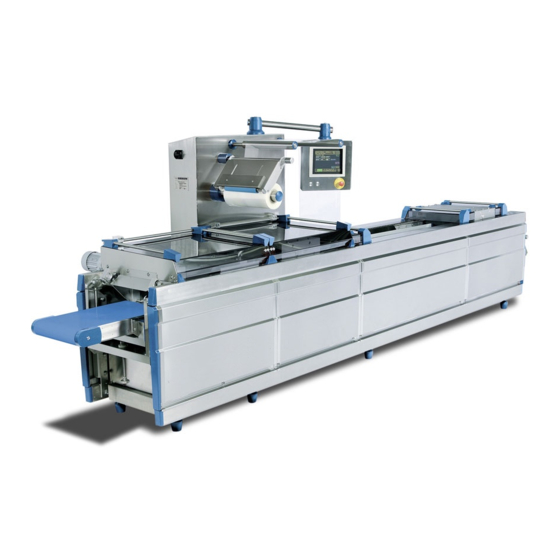
- Page 1 User Manual for the start-up and operation of the Thermoforming Packaging Machine part 1: operator Repak Phileas Foggstraat 18, 7821 AK EMMEN, The Netherlands. Phone +31 (0)591 668010, Fax +31 (0)591 676076, www.repak.nl...
- Page 2 Repak RE20 User Manual part 1: operator Machine number: 2080791 Production date: 20-02-2020 User Manual for RE20 Machine manufacturer: Service department address: Language: English Repak B.V. Repak B.V. Phileas Foggstraat 18 Version: 2.165b 7821 AK Emmen Publication date: Jan 2019...
- Page 3 Foreword The Repak RE20 is a modern deep drawing packaging machine for large to very large numbers of packages. Its modular construction, designed for optimum hygiene, makes it capable of handling a wide variety of applications. This manual is divided into three parts: the operator manual (chapter 1), the technical part with electrical and pneumatic diagrams (chapter 2 -11) and the spare parts list .
- Page 4 Telephone +31(0)591-668010 Hereby declares, completely under its own responsibility, in relation to the following machine: Horizontal shaping, filling and sealing machine, Repak RE20, RE2080791 That it meets the applicable essential requirements of the Machinery Directive (2006/42/EG) That, in addition to the abovementioned Directive, the machine meets the conditions in the following Directive (s):...
-
Page 5: Table Of Contents
Table of contents Introduction ......................6 Function ........................... 6 Most important parts ......................7 Control equipment ......................8 Technical specifications ....................9 Preventive measures and safety instructions ..........13 General safety instructions .................... 13 Intended use and use not recommended ..............15 Meaning of the symbols .................... -
Page 6: Introduction
1 Introduction Function The Repak RE20 is exclusively designed for the packaging of foodstuffs, consumables and officially registered drugs (both must meet the local recommendations and laws applicable locally) in hermetically sealed packs. In order to achieve this the machine works as follows: film is held between two chains at the infeed of the machine. -
Page 7: Most Important Parts
Most important parts A diagrammatic figure of the machine is given below (Figure 1.1). The machine consists of the following main parts: Figure 1.1 bottom film unwind unit forming station sealing station control panel control cabinet top film unwind unit cross cutting unit longitudinal cutting unit conveyor belt... -
Page 8: Control Equipment
Control equipment The machine is mainly run from the control panel fitted to the control cabinet. All the machine’s functions, such as temperature or choice of packaging program, can be operated via a touch screen (see Figure 1.2). Touch screen Emergency button start button stop button... -
Page 9: Technical Specifications
90PSI, 35 CFM 4 bar 6 bar Relative humidity System characteristics Dimensions (l x w x h) RE20: 4000-5000-6000 x 1050 x 1950 mm. Weight ca. 2200-2600 kg (incl. Vacuum pump) Film unwind unit single-sided suspension, passive braking Conveyor belt drum motor, max. - Page 10 1.4.1 Performance The performance of the machine is indicated for use under normal conditions. This implies the following: The machine is used in a roofed industrial hall that can be closed off so that both machine and operator are protected from the outside environment and from third- party activities;...
- Page 11 1.4.3 Disposal of the Repak machine Final decommissioning and disposal requires the complete disconnecting of the entire power supply system. At the end of its service life, the machine should be dismantled properly and disposed of in accordance with national regulations.
- Page 12 Contents Preventive measures and safety instructions ..........13 General safety instructions .................... 13 Intended use and use not recommended ..............15 Meaning of the symbols ....................16 Safety systems ....................... 19 2.4.1 Protection covers ....................20 2.4.2 Metal cover plates ....................21 2.4.3 Side plates ......................
-
Page 13: Preventive Measures And Safety Instructions
Shutting off the air supply immobilizes the moving parts and the blades. Repairs are to be carried out exclusively by Repak or by an expert trained by Repak. It is not allowed to make adjustments to the machine without written approval from Repak B.V. - Page 14 When turning off the main switch (see Figure 2.2) secure it with a lock in order to prevent unforeseen switching on or off by other persons. Figure 2.2 Main switch Supplementary installations such as labelling equipment, filling machines, printing equipment etc. usually have their own power supply. This should be turned on and off separately during maintenance work according to the manuals applicable to the equipment.
-
Page 15: Intended Use And Use Not Recommended
Failure to follow these rules can lead to serious accidents. Repak BV cannot be held responsible for accidents resulting from a failure to follow these rules or any other warning stated in this manual. -
Page 16: Meaning Of The Symbols
Meaning of the symbols The machine has several danger zones. A danger zone is an area where various types of danger are present that can seriously wound the person using the machine. Figure 2.3 indicates the various danger zones and warnings. Figure 2.3 Danger Zones No.: Machine part:... - Page 17 Safety plates and covers make it impossible to come into direct contact with most of the danger zones. Warnings are given in this manual relative to specific dangers in each zone. These warnings are repeated on the safety covers (see Figure 2.4). The dangers existing within each zone are explained in Table 2.
- Page 18 Meaning DANGEROUS! Rotating blades Danger (Rotating) blades can cause cuts or amputate limbs. Recommendation Do not carry out any activities within the reach of the blades. Never take hold of blades by the cutting edge. Always place blades in a safe place. NB! The sealing die bottom part has blades on the gas channels.
-
Page 19: Safety Systems
Safety systems The machine is fitted with a number of safety systems. The systems consist mainly of plastic covers, metal covers and side plates (see Figure 2.4). In addition to the main switch, the pressure switches and the over-pressure valves are part of the safety system. Figure 2.4 Safety systems Removable safety covers: sealing station;... -
Page 20: Protection Covers
2.4.1 Protection covers The 5 cover plates on the machine screen dangerous components from the outside world (see Figure 2.5). Figure 2.5 Cover plates Because of this, the machine can only be switched on when all the plates are in place. To this end the removable plates are fitted with magnets and the machine has magnetic sensors. -
Page 21: Metal Cover Plates
2.4.2 Metal cover plates Metal cover plates cover the space between the frame and the chain guide on the upper side of the frame. These plates must always be in place when the machine is in use. They may only be removed during cleaning operations. Each plate has a block that fits between the frame and the chain guide and prevents the plate from shifting. -
Page 22: Emergency Switch
Open all the clip fasteners (so that they are horizontal). Slide the upper edge of the side plate into a beam of the upper frame. Place the oblique underside of the side plate on the lower frame. Press the side plate’s contact edge against the lower frame. Lock the side plate in place by turning the clip fasteners a quarter turn to the right. -
Page 23: Transportation
IMPORTANT Wrong handling of the machine during relocation could do serious damage to the machine and endanger present personnel. Repak BV cannot be held responsible for accidents resulting from a failure to contact the supplier. - Page 24 Contents Description of the machine ................26 Operation ........................26 Description of machine frame ..................27 Description of bottom film unwind unit ................28 3.3.1 Film tracking adjustment ..................28 3.3.2 WP-400 bottom unwinder ..................29 3.3.3 CK-400 bottom unwinder..................30 3.3.4 Jumbo bottom unwinder ..................
-
Page 26: Description Of The Machine
3 Description of the machine The construction of the machine is based on modules. A rigid frame is used with suspension buses on which the modules are hung. In consequence the machine can easily be adapted to meet the customer’s specific requirements. In addition, only the frame is in contact with the floor, which is an advantage as far as hygiene is concerned. -
Page 27: Description Of Machine Frame
The following processes are carried out in the sealing station: Pressing the outer edges of the upper and bottom film together. Creating a vacuum in the packaging. Filling the packaging with a gas to prevent the packaged product from spoiling. Sealing the packaging by melting the upper and bottom film together. -
Page 28: Description Of Bottom Film Unwind Unit
Description of bottom film unwind unit Depending on the case of application the Repak RE20 can be equipped with different types of unwinders, all types are situated at the infeed side of the machine. The unwinding systems can be divided in the following types:... -
Page 29: Bottom Unwinder
3.3.2 WP-400 bottom unwinder This is the most basic type of unwinding (see fig. 3.4). The film placed on the WP-400 unwinder can be routed via 3 rollers (see routing picture), appending of film type, the routing can be changed. The routing showed in this picture is best for rigid film types, this creates more tension during unwinding and results in a smoother film infeed. -
Page 30: Bottom Unwinder
3.3.3 CK-400 bottom unwinder The CK-400 unwinder is equipped with tension arm and brake system to ensure a constant film tension during unwinding (see fig 3.5). Place the film roll so far on the spindle till the core reaches the cone on the end of the spindle. Now activate the clamp system by turning the serrated knob to the right. -
Page 31: Jumbo Bottom Unwinder
3.3.4 Jumbo bottom unwind The Jumbo unwind is meant for fast production lines with a high output. When the machine runs with thick and rigid film, the jumbo unwind is a great option. The Jumbo can handle film reels with a diameter up to 1200mm!. This device will be delivered with two exchangeable carriages, on each a film reel can be placed, so a reel change can be carried out very quickly. -
Page 32: Description Of Forming Station
Description of forming station The forming station is the place at the in-feed end of the machine frame (see figure 3.7) top part bottom part lifting system cylinder Figure 3.7 Forming station This is a composite drawing showing the various components of the forming station. The film is situated between the forming die top part and the forming die bottom part and is ready for processing. -
Page 33: Forming Station Top Heating
3.4.1 Forming station top heating The film is heated and shaped in a single advance as already described. In this device the heating plate is positioned in the forming die top part. When the device is closed, the film is pressed against the heating plate by compressed air. -
Page 34: Description Of Loading Area
Description of loading area The loading area is the area between the forming and sealing station (see Figure 3.8). Figure 3.8 Loading area This is a free area where the product to be packed is placed in the shaped package just produced. The product is put in the package by an operator or an external loading device. - Page 35 before the support bars can be removed. (To see how to shift the servo manually to another position see paragraph 4.4.12) The packages also require support following the loading area. This is achieved with shorter product support bars (see figure 3.9, pos. 3.) The crosscutting is situated on the outfeed extension.
-
Page 36: Confirmation Station
3.5.2 Confirmation station The confirmation station is situated in the loading area, It is an optional device which is specially developed to support the formed packages during filling.(see figure 3.10). The confirmation station can be (de)activated in menu option 2. The unit consists of a lifting device (on which a synthetic box is placed with the same forming index as mounted in the forming station), a vacuum pump and a vacuum valve combined with ventilation valve. - Page 37 Loading mask Lifting pin Lifting system Figure 3.11 Loading mask...
-
Page 38: Top Film Unwinding Unit
Top film unwinding unit The top film unwinding unit is fitted to the control cabinet (see Figure 3.12). There are two types of top film unwinds, the WP400 and the CK400. Figure 3.12 WP-400 top film unwind The film that is unwound here travels via the top film infeed roll onto the bottom film. Its functioning is the same as described in paragraph 3.3.2 Photocell and film brake When a printed top film is used a photocell and a film brake (see Figure 3.13) ensure that the... -
Page 39: Usage And Application Of Printed Topweb
3.7.1 Usage and application of printed top web This discusses how the tolerance of the repeat print design on packaging material for Repak Roll stock machines is determined. The tolerance is depending on the properties of the packaging material and the manner it is used on the machine. -
Page 40: Print Mark
3.7.3 Print mark 3.7.3.1 Contrast: The color of the print mark must contrast with the base colour of the film. 3.7.3.2 Division, dimensions. We recommend placing the print marks at the outside (non sealing side) of the film. For division and dimensions, see format drawing. In case of transparent film the print marks must be placed at the outside (non sealing side) of the film. -
Page 41: Tolerance Of Print Marks By Using Film Brake
3.7.4 Tolerance of print marks by using film brake (Film is pulled into the machine by stretching the film to a greater or lesser degree) 3.7.4.1 Non-stretchable packaging material. for instance paper, cardboard, PVC, aluminum foil, etc. relative total deviation Δ U: 0 up to -0,15 % (0 up to -1,5 mm on 1.000 mm) Absolute individual deviation:... -
Page 42: Description Of Sealing Station
Description of sealing station In the sealing station the filled packages are sealed with top film (see Figure 3.14). top part bottom part lifting gear cylinder Figure 3.14 Sealing station The filled packages are drawn into the sealing station and closed by the sealing die bottom part. -
Page 43: Cross Cutting
Cross cutting Depending on the application the Repak RE20 can be equipped with various cross cutting facilities. The cross cutting systems can be divided in the following groups: Flexible film cutter Film puncher Strip puncher 3.9.1 Flexible film cutter Cross cutting involves separating the sealed packages from one another in a crosswise direction. -
Page 44: Method Of Operation
3.9.1.1 Method of operation The cutting support lifts from below by pneumatic cylinder and clamps the film tight. Compressed air is injected into a membrane in the top half which pushes the blade holder and blade down to cut. After the cutting operation, the compressed air supply is cut off and the springs push the blade holder back. - Page 45 Knife blade “zigzag cut” With this knife form it is possible to attach an opening aid to the packages. Important: It is only possible to install knives of the same thickness into the knife assembly. If you, for example, would like to change a “straight” toothed knife against a “zigzag”...
-
Page 46: Film Puncher
3.9.2 Film punch The film punch (see fig. 3.17) separates the film in the across machine direction. It is used for packages with straight cuts, round corners, round holes and “Euro holes”. The punch is suitable for any kind of film or combination (such as rigid films, multilayer aluminum films and flexible films). -
Page 47: How To Adjust The Puncher. (Fig. 3.18)
3.9.2.2 How to adjust the punch. (fig. 3.18) 1. Position the punch bottom part in the right position, in between 2 packages. 2. Level both nuts “A” to an equal height and place top part. Adjust nuts “A” only as deep as necessary, so when Important: pressure bar “C”... -
Page 48: Complete-Cut Punch (Only Available For Re25!)
3.10 Complete-cut punch (only available for RE25!) The complete-cut punch is situated in the machine extension and is mounted in the machine frame. (see fig. 3.20) All packages which are made in one complete stroke will be punched completely out of the film. -
Page 49: Longitudinal Cutters
3.11 Longitudinal cutters Depending on the application the Repak RE20 can be equipped with various longitudinal cutting facilities. The longitudinal cutting systems can be divided in the following groups: Rotary knives Squeezing knives Roll and shear strip cutter Roll and shear line cutter 3.11.1 Rotary knives... -
Page 50: Squeezing Knives
3.11.2 Squeezing knives (mash knives) The squeezing knife cutter separates the packages completely from each other in the longitudinal direction (see Figure 3.22.) Film direction Air cylinders Figure 3.22 Squeezing knife assembly This knife assembly is mounted on the discharge extension of the machine The squeezing knife cutter is suitable for any kind of film or combination (such as rigid films, multilayer aluminum films and flexible films), and works fiber- and dust free. -
Page 51: Roll And Shear Strip Cutter
3.11.3 Roll and shear strip cutter The roll and shear strip cutter separates the packages completely from each other in the longitudinal direction by removing a 4mm strip from between them. (see Figure 3.24.) This longitudinal cutting device is mounted on the discharge extension of the machine. Figure 3.24 Roll and Shear exchange unit The Roll and Shear strip cutter is suitable for any kind of film or combination (such as rigid films, multilayer aluminum films, paper and flexible films), and works almost fiber free. -
Page 52: Roll And Shear Line Cutter
3.11.4 Roll and shear line cutter The Roll and Shear line cutter separates the packages completely from each other in the longitudinal direction. (see Figure 3.27.) This longitudinal cutting device is mounted on the discharge extension of the machine. The Roll and Shear line cutter is suitable for any kind of film or combination (such as rigid films, multilayer aluminum films, paper and flexible films), and works almost fiber free. -
Page 53: Discharge Conveyor Belt
3.12 Discharge conveyor belt The conveyor is situated at the discharge extension of the machine (see Figure 3.29) Figure 3.29 Discharge conveyor It transports the packages that have been cut loose. The conveyor is adjustable for the height of the packages. The conveyor belt should not be adjusted while the machine is running. At the end of the conveyor the products have to be removed from the belt by another conveyor belt, a person or a robot. -
Page 54: Control Cabinet
3.13 Control cabinet The control cabinet is situated on the side of the machine (see Figure 3.30). Figure 3.30 Control cabinet The cabinet contains the operating equipment for the various systems and processes in the machine. The control cabinet has connections for compressed air, electricity, water and gas (see Figure 3.31). -
Page 55: Drive Gear
3.14 Drive gear The drive chains are powered by an electric motor (see Figure 3.32). The chain wheels are mounted on a shaft. This causes the chains always to run at the same speed. There are two chain tensors in the drive gear. If the chain tension is too high or too low, it can be easily adjusted with the adjusters. -
Page 56: Film Edge Trim Removal
These are removed by a film trim removal unit. The installation performing this task is part of the machine. Depending on the application the Repak RE20 can be equipped with various film trim removals. The edge trim removal systems can be divided in the following groups: Film edge trim suction unit (see Figure 3.33). -
Page 57: Film Edge Trim Rewinder
3.15.2 Film edge trim rewind unit This system can be used to remove the film trim strips from longitudinal cutting units which cannot be handled by the vacuum trim removal unit (see Paragraph 3.11.3.2). 3.15.2.1 Method of Operation The film trim will be rewound by two electrically-driven motors. These motors will be controlled by a photoelectric sensor. - Page 58 Contents Control panel ...................... 59 How the touch screen works ..................59 4.1.1 Picture matrix ....................... 60 Machine operating menus ....................61 4.2.1 Read-out functions ....................62 4.2.2 Retrieval and write functions ................62 4.2.2.1 Numeric Keypad................... 63 4.2.2.2 QWERTY Keypad ................63 4.2.3 Switching functions ....................
-
Page 59: Control Panel
4 Control panel The machine is fitted with a rotating control panel mounted on the control cabinet (see Figure 4.1). Figure 4.1 Control panel The panel consists of a start switch, a stop switch, an emergency stop switch and a touch screen. -
Page 60: Picture Matrix
4.1.1 Picture matrix Figure 4.1 Picture matrix... -
Page 61: Machine Operating Menus
Machine operating menus The operator menu is the first to be displayed when the machine is turned on (see Figure 4.3). Figure 4.3 Operator menu All submenus can be accessed from the operator menu simply by touching the green areas in the menu of your choice on the touch screen. -
Page 62: Read-Out Functions
4.2.1 Read-out functions The read-out functions are displayed in the top part of the screen (see Figure 4.4). Figure 4.4 Read-out functions In this part the following information is displayed: Strokes/min: the number of production strokes that the machine is performing per minute. -
Page 63: Numeric Keypad
4.2.2.1 Numeric Keypad In addition to the main menu, the Keypad is available in every menu where numeric input is required. When this button is pressed, the keypad shown below is displayed (see Figure 4.6). Figure 4.6 Numeric keypad The value displayed in the input field selected can now be changed. The arrow keys enable the user to navigate from the current input field to other input fields. -
Page 64: Switching Functions
4.2.3 Switching functions The buttons in group D (see Figure 4.8.) are similar to main switches. Figure 4.8 Switching functions A number of functions such as adding gas to a package or automatic filling can be turned on and off centrally here. Some functions can only be switched on if the packaging program chosen permits this, so that a function cannot be switched on unintentionally. -
Page 65: Operator Menu
Operator menu The Operator menu (see Figure 4.9) is in the lowest level in the menu structure. In this level the operator can only see the values but is not allowed to change them, except the parameters listed below: Program change Pause time Switch point Vacuum Switch point Gas... -
Page 66: Operator Submenu
4.3.1 Operator submenu The operator submenu (see Figure 4.10) appears when you press on the spot where arrow “1” is pointing at the touch screen. Figure 4.10 Operator submenu You are still in operator level. Here the operator finds all the info and settings he needs to run the machine for daily production. -
Page 67: Program Choice
4.3.2 Program choice This menu is accessed by pressing the ‘PROGRAMS’ button in the operator submenu (see Figure 4.11). Program 11 1 Sauces 125 gr. Program 12 2 Sauces 250 gr. Program 13 Program 3 Program 14 Program 4 Program 15 Program 5 Program 16 Program 6... -
Page 68: Settings Menu
4.3.3 Settings menu This menu is accessed by pressing the ‘SETTINGS’ button in the operator submenu (see Figure 4.12). Figure. 4.12 Settings menu" In this menu the pause times between the machine production strokes can be set by pressing the “-” or “+” button. By pressing next buttons pause time will be changed with 0,01 sec. -
Page 69: Operation Sequence
4.3.4 Operation sequence This menu is accessed by pressing the ‘OPERATIONS’ button in the operator submenu (see Figure 4.13). Figure 4.13 Operations sequence This screen gives the operator the information how the machine is configured, nothing can be changed in this menu it is just for information. The selected operation sequence will be lit up with a green background. -
Page 70: Language Menu
4.3.5 Language menu This menu is accessed by pressing the ‘LANGUAGE’ button in the operator submenu (see Figure 4.14). Figure 4.14 Language menu In this screen you can change the language for the touch screen. The flag symbol stands for the relative country. Press one of the symbols, and the relative language will be active. -
Page 71: Miscellaneous Menu
4.3.6 Miscellaneous menu This menu is accessed by pressing the ‘MISC’ button in the operator submenu (see Figure 4.15). Figure 4.15 Menu miscellaneous The ‘Miscellaneous’ menu (see Figure 4.15) displays the number of strokes in the current production session and the total number of strokes performed by the machine. The numeric keypad (see Figure 4.6) can be used to set the number of production strokes in the current production session. -
Page 72: Symbol Explanation
4.3.7 Symbol explanation This menu is accessed by pressing the ‘Explanation Symbols’ button in the operator submenu (see Figure 4.16). Figure 4.16 Explanation of Symbols This screen shows you the explanation of the symbols which are used and is just for operator information, nothing can be changed in this menu. -
Page 73: Overview Menu
4.3.8 Overview menu This menu is accessed by pressing the ‘OVERVIEW’ button in the operator submenu and in the main menu(see Figure 4.17). Figure 4.17 Overview menu The Overview menu (see Figure 4.17) shows the status of the forming station, the sealing station, the cross cutter and the film transport. -
Page 74: Safety Guards
4.3.9 Safety guards This menu is accessed by pressing the ‘SAFETY COVERS’ button in the operator submenu (see Figure 4.18). Figure 4.18 Safety guards The Safety covers menu has indicators showing the various safety guards. When an indicator lights up green, this means that the guard is properly in place. If a guard has been incorrectly placed, the machine displays an error message, which signals which guard it is. -
Page 75: Main Menu
Main menu The main menu can be accessed by pressing, in the operator menu, the button “MAIN MENU” a little password screen will appear, press the white spot and a keypad will appear. After you fill in the right code press “ENTER”, it will go back to password screen, press “OK” and you’ve VACUUM VALVE Figure 4.19 Main Menu... - Page 76 NOTE: The access to level 2 is accepted for only 15 minutes, after this time you go back automatically to operator menu.
-
Page 77: Programs
4.4.1 Programs This menu is accessed by pressing the ‘PROGRAM’ button in the main menu (see Figure 4.20) Program 11 1 Sauces 125 gr. Program 12 2 Sauces 250 gr. Program 13 Program 3 Program 14 Program 4 Program 15 Program 5 Program 16 Program 6... -
Page 78: Operations
4.4.2 Operations This menu is accessed by pressing the ‘PROGRAM’ button in the main menu (see Figure 4.21) Here various programs can be chosen. Figure 4.21 Operations sequence The programs can only be chosen when they are valid for the type of machine. 4.4.2.1 Forming programs No Forming:... -
Page 79: Options 1
4.4.3 Options 1 This menu is accessed by pressing the ‘OPTIONS 1’ button in the main menu (see Figure 4.22) The option menu is divided in two pages, “Options 1” and “Options 2”. Figure 4.22 Options 1 Here all availible cutting options can be selected, 1 Position = To be able to cut on position with the crosscut positioned with pneumatic activated cylinder. -
Page 80: Options 2
4.4.4 Options 2 Here various options can be activated Figure 4.23 Options 2 In this menu you can select the options you need in the current program, the selected function lights up when activated. If not selected, the function buttons on operator menu will not function. = Process with filler, (synchronised) Label 1 Label 2... -
Page 81: Temperature Settings
4.4.5 Temperature settings This menu is accessed by pressing the ‘TEMPERATURE’ button in the main menu (see Figure 4.24) Figure 4.24 Temperature In this screen you can change the values for the temperature of sealing and forming station The values under ‘SP’ (Set Point) are the temperatures set for the current program. The values under ‘PV’... -
Page 82: Forming Times
4.4.6 Forming times This menu is accessed by pressing the ‘FORMING TIMES’ button in the main menu (See Figure 4.25) Figure 4.25 Forming times In this screen you can see the time set points (SP), and the pressure set points for the forming chamber (forming station) The value of the set points can be changed by pressing the numbers in the left column;... -
Page 83: Forming Times (With Plug Assist)
4.4.7 Forming times (with plug assist) This menu is accessed by pressing the ‘FORMING TIMES’ button in the main menu (See Figure 4.26) Figure 4.26 Forming times In this screen you can see and change all time set points (SP), for a forming chamber (forming station) with plug assist. -
Page 84: Miscellaneous
4.4.8 Miscellaneous This menu is accessed by pressing the ‘MISCELLANEOUS’ button in the main menu (see Figure 4.27) Figure 4.27 miscellaneous This screen allows you to view indexes or advances (strokes) per day and life of the machine. You can reset the machine strokes; you can not reset the total nr. of strokes Stop after XX strokes: If active then machine will stop after set value. -
Page 85: Die Opening
(see Figure 4.28) Figure 4.28 Die opening To speed up the process time, the RE20 has the possibility to adjust the opening of each die,. As standard the lifting stations return to their lowest positions however when a time which is entered is shorter then the time needed to open completely, the opening distance will be shorter. -
Page 86: Depth Adjustment
4.4.10 Depth adjustment* This menu is accessed by pressing the ‘DEPTH ADJUSTMENT’ button in the main menu (see Figure 4.29) Figure 4.29 Depth adjustment Here the desired depth of the forming chamber can be established. The set value has a tolerance of ±2 mm. -
Page 87: Leak Detection
4.4.11 Leak detection* This menu is accessed by pressing the ‘LEAK DETECTION’ button in the main menu (see Figure 4.30) Figure 4.30 Leak detection The machine can be supplied with leak detection in the forming station. Leak detection works together with the filler synchronisation. Upon the detection of a leaking package the filling signal to the filler is prevented so no product is filled into it. -
Page 88: Traject Control
Figure 4.31) Figure 4.31 Alarm History Traject control is a special option in the RE20 to control the packages all through the machine It starts at the forming station in combination with “Leak detection” (see Figure 4.30). In this menu the positions for filler and sealing station has to be set, the input value has to be the number of strokes between forming chamber and filler position, and forming chamber and sealing station. -
Page 89: Vacuum Settings
4.4.13 Vacuum Settings This menu is accessed by pressing the ‘VACUUM SETTINGS’ button in the main menu (see Figure 4.32) Figure 4.32 vacuum settings Here you can change all vacuum settings for sealing station. Switch point vacuum: =The vacuum pressure switch level in mbar for machine operation. -
Page 90: Vacuum Graphic
4.4.13.1 Vacuum Graphic This menu is accessed by pressing the ‘VACUUM GRAPHICS’ button in the vacuum settings menu (see Figure 4.33) Figure 4.33 Vacuum Graphic This screen shows you a real time vacuum curve of each vacuum and gas process. Press button return and the screen goes back to the screen vacuum settings. -
Page 91: Vacuum Times
4.4.14 Vacuum times This menu is accessed by pressing the ‘VACUUM TIMES’ button in the main menu (see Figure 4.35) Figure 4.35 Vacuum times This screen shows you all time settings for the vacuum chamber (seal station). Delay vacuum bottom: = Waiting time before the bottom vacuum start its process. -
Page 92: Cross Cutting Times
4.4.15 Cross Cutting Times This menu is accessed by pressing the ‘CROSS CUTTING TIMES’ button in the main menu (see Figure 4.36) Figure 4.36 Cross Cutting Times This screen shows you all time settings needed for the cross cuttings process. 4.4.15.1 Guillotine This cutting process can be divided into 3 steps with a delay time in between. - Page 93 Punch up/down button is only visible when in configuration one or more punches are selected and when in configuration/”invert sensors ( see figure” the button has been released. Button “change of punch anvil” has been released. Button “change of punch anvil” is not released. The value of the set points can be changed by pressing the numbers.
-
Page 94: In-Liner
4.4.16 In-liner* This menu is accessed by pressing the ‘INLINER’ button in the main menu (see Figure 4.37) Figure 4.37 In-liner This screen shows you all time settings needed for the in-liner process. Discharge time in-liner: = Running time overall When there are no packages to detect or photocell is out of order, the lanes will run for this set time. -
Page 95: Servo Cross Cutting
4.4.17 Servo Cross Cutting* This menu is accessed by pressing the ‘SERVO CROSS CUTTING’ button in the main menu (see Figure 4.38) Figure 4.38 Servo Cross Cutting This screen shows you all settings needed for the servo cross cuttings. First crosscut position = Distance in mm. -
Page 96: Complete Cutting
4.4.18 Complete cutting This menu is accessed by pressing the ‘SERVO CROSS CUTTING’ button in the main menu (see Figure 4.39) Figure 4.39 Complete Cutting This screen shows you all settings needed for the complete cutting device. Discharge time conveyor : The running time for the integrated conveyor after film advance. -
Page 97: Alarms
4.4.19 Alarms This menu is accessed by pressing the ‘ALARMS’ button in the main menu (see Figure 4.40) Figure 4.40 Alarm History This screen shows the last 1000 alarms with a time span. -
Page 98: Maintenance
4.4.20 Maintenance This menu is accessed by pressing the ‘MAINTENANCE’ button in the main menu (see Figure 4.41) Figure 4.41 Maintenance This screen gives you access to several menus, and functions. Night position: = The die sets close and the temperature goes to 30°C. to prevent condensation and cleaning water in the die sets (use this function after production). -
Page 99: Chain Cleaning
4.4.20.1 Chain cleaning When the machine is operating in a very wet and/or salty area, the machine can equipped with a Chain Cleaning System, therefore a cleaning program is added to the software. When this system is installed into the machine this function will start by activating “Cleaning chain” button in the maintenance menu. -
Page 100: Vacuum Test
4.4.20.2 Vacuum test This menu is accessed by pressing the ‘VACUUM TEST”’ button in the maintenance menu (see Figure 4.42) Figure 4.42 Service Here the vacuum process is shown in a graphic. Machine has to be set into manual mode, and also the pump must be in run. -
Page 101: Access Code
4.4.20.3 Service This menu is accessed by pressing the ‘SERVICE’ button in the main menu (see Figure 4.43) Figure 4.43 Service If you press Transport, Configuration or Servo System button in Service menu, you will be asked for a password, type the right password to enter the other menus. After you fill in the right code press enter, it will go back to password screen, press ok and you are in the relative menu. - Page 102 Contents Operating the machine ..................103 Preventive measures and safety instructions .............. 103 5.1.1 Instructions ......................103 5.1.2 Emergency switch ....................105 Turning on the machine ....................106 5.2.1 General points to be checked ................107 5.2.2 Automatic operation ................... 108 5.2.3 Film infeed ......................
-
Page 103: Operating The Machine
5 Operating the machine This chapter describes how the machine should be used. Use of the control panel has already been described in Chapter 4. The present chapter goes into greater detail regarding the steps to be taken to get the production process running and how to stop it. For each part of the machine the user is referred to the general safety regulations (see Chapter 2) and specific recommendations that are given. - Page 104 The next lubricants for the machines must be used: Lubrication of Transportchain; Bell Ray No Tox Food Grade Waterproof Chain Lubricant 2 OL Vat Vacuumpump Busch; Bush VM 100 (Öl nach DIN 51506,Schmierölgruppe VM) Grease lubricant (Liftingsystem and Vario die cutter); Anderol 783-2 food grade grease, Anderol Item #ANO7832039 Canada...
-
Page 105: Emergency Switch
5.1.2 Emergency switch When danger threatens, always press the emergency switch immediately. The emergency switch is on the front of the control panel and can be recognized by its red color with a yellow edge below (see Figure 5.1). There may also be emergency switches at other points on the machine. -
Page 106: Turning On The Machine
Turning on the machine Staged plans have been drawn up for turning the machine off and on. The plans include all the actions that have to be performed for turning the machine on. The machine has 2 operational modes: Automatic operation. The machine repeats the packaging process continuously and stops when a set number of strokes have been performed or the process is terminated manually. -
Page 107: General Points To Be Checked
5.2.1 General points to be checked Table 4 states general points that have to be checked before the machine is turned on. This helps prevent problems in starting up and running the machine. Table 4 Points to check when turning the machine on No. -
Page 108: Automatic Operation
5.2.2 Automatic operation This paragraph describes how an automatic packaging process can be started up (see Table 5). However the procedure does not apply if the machine has been turned off in an unconventional manner, e.g. by using the emergency switch. Other procedures apply when starting up the machine in this situation. -
Page 109: Film Infeed
5.2.3 Film infeed The staged plan for the Film infeed operational mode is described in Table 6. Table 6 Start film indeed Main switch Heating elements Afbe> Waar zit alles dan??? No. Action Remark Check that no-one else is working on or Go on to the next stage only when with the machine. -
Page 110: Single Stroke
5.2.4 Single stroke The staged plan for the Single Stroke operational mode is described in table 7. Table 7 Starting up single stroke Main switch Heating elements Afbe> Waar zit alles dan??? No. Action Remark Check that no-one else is working on or Go on to the next stage only when with the machine. -
Page 111: Re-Starting The Machine
5.2.5 Re-starting the machine There are four situations whereby the machine has (been) stopped and a re-start is possible. The stages to be gone through to re-start the machine depend on the way the production process was interrupted. To re-start the machine appropriately, follow the staged plan applicable to the type of interruption that has taken place. -
Page 112: Fitting The Rolls Of Film
Fitting the rolls of film The machine uses 2 rolls of film for packaging the products: a lower and an top film. First a description is given of the step-by-step procedure for fitting the bottom film and then for fitting the top film. - Page 113 Place the roll of film on its shaft. See Figure 5.5. Get help with lifting the roll of film. Replace the film guide on the film roll. Line up the film roll. Use the setting button (see Figure 5.5) and fix it with the lock nut. Make sure that the setting button does not turn while being locked.
-
Page 114: Top Film
5.3.2 Top film Table 9 gives a step-by-step description of how the top film should be positioned. The main switch must be turned on but no packaging process may be performed. Avoid bumping against the projecting parts of the control cabinet by taking care during work on the top film. -
Page 115: Setting The Photocell
Setting the photocell The machine can be equipped with a photocell that is used for packaging with a printed top film (see Figure 5.7). film brake housing film roll photocell star grip Figure 5.7 Setting the photocell During transport of the film the top film passes a photocell that detects marks on the film. Usually a top film packaging length is slightly shorter than the stroke length (see also paragraph 3.2.9). -
Page 116: Calibrate The Photocell
Calibrate the photocell The photocell must be calibrated by using the following steps (see Figure 5.8) Setting the photocell for mark and background, A two-step setup procedure adjusts the switching threshold and the LIGHT/DARK mode. Using the procedure below, the sensor output is set to be ON when a mark is detected. Output ON state acquisition (MARK) Place the target mark into the emission spot and press the MARK button until the green LED turns OFF. -
Page 117: Turning The Machine Off
Turning the machine off Depending on the time that the machine needs to be shut down, various procedures apply as regards turning it off. In Table 10 a distinction is made between three shutdown periods: Turning off for a brief period, e.g. to replace film, means that the machine is on standby. -
Page 118: Energy-Saving Operation
When filling the packages, the operator may work only in the area indicated between the covers (see Figure 5.9). It is not permitted to have body parts under the covers. Figure 5.9 Loading area Energy-saving operation In order to lessen the burden on the environment, it is a good idea not to leave the machine turned on needlessly. - Page 119 Contents Cleaning and maintenance ................120 Guidelines and methods ....................120 6.1.1 Cleansers ......................120 6.1.2 Washing setting ....................121 6.1.3 Disinfecting and removing calcium deposits ............121 Maintenance procedures....................121 Maintenance instructions ..................... 126 6.3.1 Conveyor chain ....................126 6.3.2 Lifting stations ....................
-
Page 120: Cleaning And Maintenance
To get rid of calcium deposits only cleansers based on citric acid may be used. Use disinfectants only based on alcohol. The use of cleansers or disinfectants based on chlorine is not permitted. If you have questions about cleansers, please consult your Repak agent. WARNING When using cleansers, avoid skin contact and wear protective garments as described on the packaging. -
Page 121: Maintenance Procedures
6.1.2 Washing setting The machine has a special setting for cleaning purposes. You can select this setting from the main menu. It has the following characteristics: The format parts are closed. This protects them from cleansers and flooding. The heating plates cool down to 30 C/ 86 F WARNING The format parts can remain hot up to 1 hour after being turned off. - Page 122 WARNING Serious neglect in carrying out the recommended maintenance work causes the machine’s warranty to lapse. WARNING Take care that nobody unexpectedly turns the machine on during cleaning operations. A number of parts of the machine carry a higher hygiene risk (see Figure 6.1): Always clean these very carefully! 1.
- Page 123 Procedure 1: Preparations Tools required: scissors/knife Chain clips lifting gear for film rolls waste bin adhesive tape Transport chain protection film No. Action Remark Remove any film still in the machine by using See paragraph 5.3. the transport button on the control panel. Save the remains of film for point 13.
- Page 124 Use film to cover parts sensitive to water, such Avoid as far as possible any as motors, control panel, labeling machines direct contact with water. and vacuum pump. Fix the film in place with adhesive tape if necessary, but ensure that the parts cannot flood.
- Page 125 compressed air waste bin chain oil small brush screw driver Chain clips Transport chain Figure 6.3 RE20 protective plates side plates bottom film infeed roller product support bars support tray longitudinal cutter crosswise cutting...
-
Page 126: Maintenance Instructions
Maintenance instructions Before working on the machine, first ensure that the machine is switched off (disconnect the power cable and remove the safety cover). Take care with the pneumatic installation! Read the manual for the safety instructions. Work can be started as soon as all necessary precautions have been taken. Only qualified mechanics may work on the machine! After the activities, ensure that the machine is in proper condition. - Page 127 The above scheme applies for machines operating under normal operating conditions. The lubricating intervals must be adapted, depending on conditions and operating intensity. For this reason, Repak advises weekly visual inspection of the chain. If in doubt, consult the distributor.
-
Page 128: Lifting Stations
6.3.2 Lifting stations Lifting stations As a rule, two lifting stations are fitted in a machine. One for the forming station and one for the sealing station. These lifting stations require little maintenance. There are two kinds of lifting stations. A standard aluminium lifting station, and a heavy duty stainless steel lifting station. - Page 129 Figure 6 Aluminium lifting station lubrication nipples Figure 7 Stainless steel lifting station lubrication nipples Repak advises lubricating the entire lifting station once a week. This lubricating scheme applies for machines operating under normal operating conditions. The lubricating intervals must be adapted, depending on conditions and operating intensity.
-
Page 130: Hard Foil Stamp
6.3.3 Hard foil stamp Preparatory activities Before carrying our maintenance work, check the hard foil stamp for damage, contamination and corrosion. Remove any film and / or product residue. If applicable, use the key switch for safe operation of the hard foil syamp. Read the instructions for more information on the key switch. If in doubt, consult the distributor. - Page 131 Lubrication Repak advises fully lubricating the stamps once a week. This lubricating scheme applies for machines operating under normal operating conditions. The lubricating intervals must be adapted, depending on conditions and operating intensity. If in doubt, consult the distributor.
- Page 132 Action Remark Remove the protective covers from the Place the covers on the machine. ground because they are fragile. Remove the side plates from the machine. See paragraph 2.4.3 for Place the plates on the ground because removing the side plates. they are fragile.
- Page 133 Procedure 3: Preparing the machine for operation Tools required: - Screw driver safety covers side plates Figure 6.4 RE20 No. Action Remark Replace all components that have been removed. Replace all safety covers and protective See paragraph 2.4.3 for systems.
-
Page 134: Recording The Maintenance And Cleaning Logbook
Recording the maintenance and cleaning logbook Type of maintenance Date Name Signature Remarks... - Page 135 Contents Overview of status lines .................. 136 Environmental factors ....................136 Overview of status lines ....................137 Defects affecting the film ....................139 Explanatory list of words ................. 140 Appendix......................144...
-
Page 136: Overview Of Status Lines
7 Overview of status lines There can be various causes of failure in the machine. Regular performance of maintenance procedures can prevent a great number of problems from arising, ranging from crumpled packaging and mechanical defects to sudden shutdown of machine systems. Solving most of the problems related to packaging quality is a matter for the technical department however a number of problems can also be solved by the operator. -
Page 137: Overview Of Status Lines
Overview of status lines A machine failure causes an error message to be displayed on the touch screen status line. Table 12 lists possible messages, their causes and the solutions. Table 12 Overview of status lines No: Message Cause Solution Start the machine according to The emergency switch has been EMERGENCY STOP... - Page 138 Analog input sensor 2 Analog input sensor 1 has failed. Check wiring and connectors. This is normal. See paragraph The machine has reached the RE20 stopped after 4.4.7 for setting the number of number of strokes set. number of strokes. strokes.
-
Page 139: Defects Affecting The Film
Standby: Ready to start information on this mode see automatic operation. paragraph 5.2.2. This is normal. See paragraph Run: RE20 in motion The machine is running. 5.6 to stop the machine. *1 are optional functions. Defects affecting the film A defect or failure not reported on screen is when the film breaks or becomes loose. If a break occurs or the film slips out of the chain, the following actions should be undertaken: stop the machine with the stop button;... -
Page 140: Explanatory List Of Words
8 Explanatory list of words Chain guide: Combination of metal and plastic profiles that guides the transport chain. Compressed air: Air at a pressure greater than 1 bar. Control panel: This panel enables the operator to run the entire machine. To this end the panel has a start and stop button, an emergency switch and a touch screen. - Page 141 System that raises and lowers the seal die and vacuum die to and from the film. Machine: This indicates the RE20 deep drawing packaging machine to which this manual refers. Magnetic switch: Consists of two magnets, one in the protective cover and one on the machine. Whenever contact between the two magnets is interrupted, the machine stops.
- Page 142 This is the side of the machine opposite the control cabinet. Operator: A person authorized and trained by Repak, its agents or distributors to run the machine. Over-pressure valve: Valve that lets in air if the pressure rises too high.
- Page 143 Support tray: Tray used to support the film. Support zone: Place on the machine where the product to be packaged is placed in the drawn-down bottom film. System cabinet: Cabinet containing the pneumatic and electrical parts that drive the machine. Only the technical department has access to these drives.
-
Page 144: Appendix
9 Appendix - TI-14-025 Vacuum pump (warm up and after running) - TI-14-032 Declaration of compliance for food contact...
Need help?
Do you have a question about the RE20 and is the answer not in the manual?
Questions and answers
What is the exact time to the vacuum.the set time that a have is 1.00 sec and seal time 3.00 sec and ventilation seal plate 0.30 sec and pause time 6.00 sec. What is the perfect set time.
The perfect vacuum setting for the Repak RE20 depends on the desired vacuum pressure level. The switch point vacuum is the pressure switch level in mbar, where 0 mbar represents an absolute vacuum (~1013 mbar below atmospheric pressure). The vacuum time is the extra time after reaching the switch point vacuum.
For sealing, the seal time setting is not explicitly mentioned in the provided context. However, ensuring proper vacuum time and switch point vacuum settings will contribute to an effective seal.
If precise values are required, they should be determined based on the specific packaging requirements and machine calibration.
This answer is automatically generated
Why the dei snaps before finish the vacuum time.
The Repak RE20 die may snap before finishing the vacuum time if the ventilation pressure or ventilation time is not properly set. Before opening the die set, the inside and outside pressure must be balanced by ventilating. If this process is not completed correctly, uneven pressure distribution can cause mechanical stress, leading to the die snapping. Ensuring proper ventilation pressure and time settings can help prevent this issue.
This answer is automatically generated
How to remove shaft where tension bock is