
Related Manuals for 3Rtablet VT-10 Pro

Summary of Contents for 3Rtablet VT-10 Pro
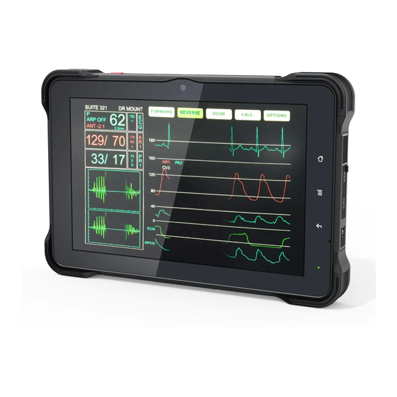
- Page 1 VT-10 Pro 10 Inch Rugged Android Vehicle Display Terminal User Manual Version 1.0.1...
- Page 2 We recommend that you keep one copy of this manual for the quick reference for any necessary maintenance in the future. Thank you for choosing 3Rtablet products.
-
Page 3: Table Of Contents
2.2.2 Checking the Battery Level................10 2.3 Optimizing Battery Life....................10 2.4 Installing Micro SD and SIM Card.................11 Chapter 3 Using VT-10 Pro Hardware Interface ..............12 3.1 Transferring Files between Computer and the Device..........12 3.1.1 Connection......................12 3.2 Using Serial Port Demo App..................13 3.3 Using ACC........................ - Page 4 RoHS 3Rtablet Corp. certifies that all components in its products are in compliance and conform to the European Union’s Restriction of Use of Hazardous Substances in Electrical and Electronic Equipment (RoHS) Directive 2002/95/EC.
- Page 5 This product is warranted to be in good working order during the warranty period. Should this product fail to be in good working order at any time during this period, we will, at our option, replace or repair it according to 3Rtablet after-sale-service terms. This warranty does not apply to products damaged by misuse, modifications, accident or disaster.
- Page 6 inability to use this product. Vendor will not be liable for any claim made by any other related party. Return authorization must be obtained from the vendor before returned merchandise will be accepted. Authorization can be obtained by calling or emailing the account representative from vendor and requesting a Return Merchandise Authorization (RMA) number.
-
Page 7: Chapter 1 Introduction
Chapter 1 Introduction 1.1 Product Highlights ● Qualcomm Cortex-A53 64-bit Octa-core processor 1.8 GHz ● Android 9.0 Operation System ● Comply with IP67 rating ● WIFI, Bluetooth, LTE, GNSS and 8000 mAh rechargeable battery supported ● 10 Inch IPS Display, physical 1280x800 resolution, 1000 cd/m², multi-point capacitive touch ●... -
Page 8: Extended Cable Definition
1.3 Extended Cable Definition 1.3.1 Docking Station NO. Item Definition COM 1 RS232 /dev/ttyHSL0. COM 2 RS232 /dev/ttyHSL1. Connect with vehicle ACC power. Voltage range: 0-30 V. Input Note: With ACC function, the device is requested to connect the power source via DC adaptor simultaneously to power on after ignition. -
Page 9: All In One Cable
1.3.2 All in one cable Item Definition COM 1 RS232 /dev/ttyHSL0. COM 2 RS232 /dev/ttyHSL1. Connect with vehicle ACC power. Voltage range: 0-30 V. Note: With ACC function, the device is requested to connect the power source via DC adaptor simultaneously to power on after ignition. please refer to 3.3 for the DEMO and source code of ACC. -
Page 10: Specifications
1.4 Specifications Specifications Qualcomm Cortex-A53 64-bit Octa-core processor 1.8 GHz Adreno 506 Operating Android 9.0 System 2GB LPDDR3(Default)/4GB(Optional) Storage 16GB eMMC (Default)/64GB(Optional) Storage Micro SD Card 128G Expansion 10 Inch Digital IPS Panel ( 1280 x 800 ) 1000 cd/m² Touchscreen Multi touch capacitive touchscreen supporting glove and rain mode Integrated microphone... - Page 11 DC-HSUPA: Max 11.2 Mbps (UL) WCDMA: Max 384 Kbps (DL/UL) 1575.42 MHz±1.023 MHz GLONASS 1597.5 MHz~1605.8 MHz GNSS 1561.098 MHz±2.046 MHz BeiDou Read/ write Made: ISO/IEC 14443 A&B up to 848 Kbit/s, Felica at 212&424 Kbit/s MIFARE 1K, 4K, NFC Forum type 1, 2, 3,4,5 tags. ISO/IEC 15693 NFC (optional) All peer-to-peer modes Card Emulation Mode (from host): NFC Forum T4T (ISO/IEC 14443...
-
Page 12: System Icon Description
OBD-II (optional) OBD-II (optional) Input × 2, Output × 2 Input × 2, Output × 2 (Default) GPIO (Positive (Default) Trigger input) GPIO × 6 (optional) GPIO × 6 (optional) Analog Inputs × 3(optional) × 3(optional) 1-wire optional optional RJ45 optional optional RS485... -
Page 13: Chapter 2 Getting Started
Proper operation of power on/off the device will be beneficial to ensure the stability of the system. The device status indicated by the color of the indicator is as described in the following table for the standard VT-10 Pro. We provide customized service if the customer has other requirements regarding the operation of switch. -
Page 14: Changing The Battery
b. Short press button to sleep. c. Sleep by ACC, see the details in Chapter “3.3 Using ACC” d. Short press to wake e. Wake by ACC, see the details in Chapter “3.3 Using ACC” f. The average of power consumption in sleep status: 1W 2.2 Changing the Battery The tablet battery is installed in a removable way, which greatly facilitates the user's use of disassembly and installation. - Page 15 ③Pull out the fixed battery groove (located on the upper right of the battery). ④After completing the above operations, as shown in the figure below.
-
Page 16: Charging With The Power Adapter
Charging the Battery”. 2.3 Optimizing Battery Life If the VT-10 Pro is unable to keep charging by DC power supply, to optimize the operating time of the battery, it is recommended that you do the following: Decrease the LCD display brightness. -
Page 17: Installing Micro Sd And Sim Card
the battery usage by individual App, swipe down the Status Bar in the upper right corner and tap and hold the Battery icon. Enable CPU power saving mode on battery settings page to limit the maximum CPU performance to conserve battery life and lower device temperature. -
Page 18: Chapter 3 Using Vt-10 Pro Hardware Interface
Chapter 3 Using VT-10 Pro Hardware Interface 3.1 Transferring Files between Computer and the Device You can transfer files, such as pictures or audio files, between your computer and your device using the provided USB cable. 3.1.1 Connection Connect the device to the computer by using the USB type-c cable, and open... -
Page 19: Using Serial Port Demo App
Find out the Device in “This PC”. “ ” 3.2 Using Serial Port Demo App Serial Port ID: COM1, COM2 Correspondence between RS232 tail line and device node. COM1=/dev/ttyHSL0. COM2=/dev/ttyHSL1. 1. The boxes in red means the text box for the COM port information received, to display information received by corresponding COM port. -
Page 20: Using Acc
10. The boxes in red means manual clear button, click to clear both info. in the COM port info. receiving boxes. 3.3 Using ACC Please see “1.3 Extended cable definition” for ACC Interface details. 3.3.1 ACC Connection Instruction Figure, connecting the tablet with vehicle power supply through extended cable or docking station, and connecting ACC wire on extended cable of the tablet with ACC of vehicle. -
Page 21: Acc Settings Path
3.3.3 ACC Settings Path Find ACC Settings from Settings as the Figures shown: 3.3.4 ACC Settings ACC Settings Path : Settings-->ACC Settings Note: The following text description corresponds to the red number in the figure. - Page 22 1. ACC controls the switch of the three functions of turning on the screen, turning off the screen and turning off the power; 2. ACC controls switch to turn off the screen function; 3. Click to pop up the dialog box in Figure to set the delay time to turn off the screen display after ACC is disconnected;...
-
Page 24: Using Gpio
3.4 Using GPIO 3.4.1 GPIO Tail Lines Instruction Regarding the definition diagram of GPIO interface, please see the details in Chapter “1.3 Extended cable definition”. 3.4.2 GPIO Specification The GPIO interface instruction diagram is as follows: Input 1 Input 2 Output 1 Output 2 GPIO... - Page 25 c) Introduction of Main Components The part marked with a red box in Figure. 1. Name: means the port names of GPIO. 2. Direction: means the input or output direction of the ports. 3. State: means the current level state of the GPIO ports. The button marked with a red box shown in Figure.
- Page 26 The button marked with a red box shown in Figure used to set the high or low of GPIO output at once.
-
Page 27: Using Nfc Function
3.5 Using NFC Function 3.5.1 NFC Activation Method Activate the NFC function according to Figure. -
Page 28: Nfc Usage Demo
3.5.2 NFC Usage Demo After activating NFC function, place the NFC card close to the induction area. A prompt tone would be heard if the card is successfully identified. If the card contains some information (such as manufacturer’s information), there will be an interface popped up as shown in figure. -
Page 29: System Root Switch Usage Guide
3.6 System Root Switch Usage Guide 1 Refer to the following figure to enter the Root privilege (on/off) function setting interface. - Page 30 2 The root switch setting interface is as follows. In the figure, 1” is the Root “ permission (on/off) switcher 2” to modify the password. . “ Initial password: “qwertyuiop”. 3 The dialog box to set the Root Permissions (on/off)
-
Page 31: Chapter 4 Docking Station Using Instruction
4 The dialog box for modifying the password required for the root permission (on/off) status Note: If restore the factory settings, the root switch state will be reset to OFF, and the password is restored to the initial. Chapter 4 Docking Station Using Instruction 4.1 Docking Station Install Steps 1.Insert the key and turn it 90 degrees to the right to unlock the key to unlock the telescopic buckle as Fig 4-1 shown. - Page 32 Fig. 4-1 2. Align the VT-10 Pro to the limit slot of docking station as Fig 4-2 shown. Fig. 4-2 3.the buckle up as the Fig.4-3 shown.
- Page 33 Fig. 4-3 4.Push VT-10 Pro to make it attached the docking via snap joint, as Fig. 4-4 shown. Fig. 4-4 5. Release and finish the installation as Fig.4-5 shown.
- Page 34 Fig 4-5 4.2 Docking Station Disassemble Steps 1. Stretch upwards the buckle to release it from the device, as Fig 4-6 shown. Fig. 4-6 2.Take out the device as Fig.4-7 shown. Fig. 4-7 3.Hold down the key and rotate 90 degrees to the locked sign, pull out the key to...
- Page 35 lock the telescopic buckle as shown in Fig.4-8. Fig. 4-8...
-
Page 36: Chapter 5 Accessories
Chapter 5 Accessories 5.1 Accessories Allen Wrench Screws for RAM USB to Type-C cable DC (12V) battery cover crowbar 5.2 Optional accessories 1. J1939 female to open cable 1 pc 2. OBD-II female to open cable 1 pc 3. RAM -101U 1 pc...
Need help?
Do you have a question about the VT-10 Pro and is the answer not in the manual?
Questions and answers