Table of Contents
Advertisement
Advertisement
Table of Contents

Related Manuals for 3Rtablet VT-7 Pro

Summary of Contents for 3Rtablet VT-7 Pro
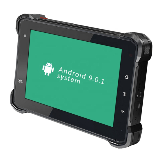
- Page 1 VT-7 Pro 7 Inch Rugged Android Vehicle Display Terminal User Manual Version 1.0...
- Page 2 If you are not sure about any description in this manual, consult your vendor before further handling. We recommend that you keep one copy of this manual for the quick reference for any necessary maintenance in the future. Thank you for choosing 3RTablet products.
-
Page 3: Table Of Contents
2.3.2 Checking the Battery Level ................ 17 2.3.3 Installing/Replacing the Battery ..............18 2.4 Optimizing Battery Life ..................19 Chapter 3. Using VT-7 Pro Hardware Interface..............21 3.1 Transferring Files between Computer and the Device ......... 21 3.1.1 Connection ....................21 3.2 Using Serial Port Demo App................. - Page 4 RoHS 3RTablet Corp. certifies that all components in its products are in compliance and conform to the European Union’s Restriction of Use of Hazardous Sub- stances in Electrical and Electronic Equipment (RoHS) Directive 2002/95/EC.
- Page 5 Should this product fail to be in good working order at any time during this period, we will, at our option, replace or repair it according to 3Rtablet af- ter-sale-service terms. This warranty does not apply to products damaged by...
- Page 6 Vendor assumes no liability for any damages, lost profits, lost savings or any other incidental or consequential damage resulting from the use, misuse of, or inability to use this product. Vendor will not be liable for any claim made by any other related party.
-
Page 7: Chapter 1: Introduction
Chapter 1: Introduction 1.1 Product Highlights ● Qualcomm Cortex-A53 64-bit Octa-core processor 1.8G ● Android 9.0 Operation System ● Comply with IP67 rating ● WIFI, Bluetooth, LTE, GNSS and 5000mAh rechargeable battery supported ● 7 Inch IPS Display, physical 1280x800 resolution, 800cd/m², multi-point capaci- tive touch ●... -
Page 8: Extended Cable Definition
1.3 Extended Cable Definition 1.3.1 Standard Version NO. Item Definition Pogo GPIO69 GPIO33 GPIO66 GPIO22 GPIO23 RXD0 TXD0 RXD1 TXD1 VUSB RS232 /dev/ttyHSL1. RS232 /dev/ttyHSL0. Connect with vehicle ACC power. Voltage range: 0-30V. Input Note: With ACC function, the device is requested to connect the power source via DC adaptor simultaneously to power on after ignition. -
Page 9: Obd-Ii Version
1.3.2 OBD-II Version Item Definition Pogo GPIO69 GPIO33 GPIO66 GPIO22 GPIO23 RXD0 TXD0 RXD1 TXD1 VUSB OBD-II Reserved Bus posi- Reserved Chassis Signal CAN_H K_line ac- Reserved tive line of ground ground line of ISO cording to SAE J1850 15765-4 ISO 9141- 2 and ISO 14230-4... -
Page 10: Sae J1939 Version
1.3.3 SAE J1939 Version Item Definition Pogo GPIO69 GPIO33 GPIO66 GPIO22 GPIO23 RXD0 TXD0 RXD1 TXD1 VUSB J1939 Battery Battery CAN/ CAN/ CAN/J1939 Protocol Protocol “ “ Minus Plus J1939 J1939 shield High”Line,i.e Low”Line,i.e (Ground) (+V) High CAN/J1708/J193 CAN/J1708/J1939 9 High RS232 /dev/ttyHSL0. -
Page 11: Can Bus Version
1.3.4 CAN Bus Version Item Definition Pogo GPIO69 GPIO33 GPIO66 GPIO22 GPIO23 RXD0 TXD0 RXD1 TXD1 VUSB Shielded Line High RS232 /dev/ttyHSL0. ACC in- Connect with vehicle ACC power. Voltage range: 0-30V. Note: With ACC function, the device is requested to connect the power source via DC adaptor simultaneously to power on after ignition. -
Page 12: Specifications
1.4 Specifications Durability Features IP67 Rating Certified 1.5m (5ft.) drop-resistance Raised bezel for LCD impact protection LCD Display Size 7 Inch Digital IPS Panel Resolution 1280 x 800 Brightness 800 cd/m² Touch screen Type Multi-point Capacitive Touch System Qualcomm Cortex-A53 64-bit Octa-core processor 1.8G Android 9.0 Memory... - Page 13 2.4GHz&5GHz Support Wake-on-WLAN (WoWLAN) Support ad hoc mode Support WAPI SMS4 hardware encryption Support AP mode Support Wi-Fi Direct Support MCS 0-7 for HT20 and HT40 2402MHz~2480MHz Bluetooth Integrated Bluetooth 4.2 LE + EDR class 2, with HID, A2DP, AVRCP, BIP, BPP, FTP, HFP, HSP, OPP, SPP supported Gyroscope Sensor...
- Page 14 GPIO×2 Input, GPIO×2 Output (See “3. 4Extended Cable Definition” for GPIO details.) (See “3. 3Extended Cable Definition” for details.) I/O Interface (J1939 /OBD-II/CAN Bus version) Serial Port 1 x RS232 J1939/OBD- (See “1.3Extended Cable Definition” for details.) II/CAN Bus USB Port 1 x USB Host,1x USB Device, High speed up to 480Mbps SD Slot 1 x Micro SD card, 1.8v / 2.95v, up to 64G...
-
Page 15: Chapter 2: Getting Started
The device status indicated by the color of the indicator is as de- scribed in the following table for the standard VT-7 Pro. We provide customized service if the customer has other requirements regarding the operation of switch. -
Page 16: Installing Micro Sd And Sim Card
DC input or USB type-C input in priority, rather than the power from the internal battery. It makes the battery to be stored after fully charged. This excellent design is very beneficial for extending the life of the VT-7 Pro battery and ensuring the safety in use. -
Page 17: Charging With The Power Adapter
DC port of Docking Sta- tion. b. The VT-7 Pro could be charged by a 5V 2A or above by USB type-C cable. Warning: Please ensure that the input voltage of the DC interface is within the range of 8V- 36V, or use the 12V adapter coming with device. -
Page 18: Installing/Replacing The Battery
b. When the battery is fully charged, you can disconnect the DC input or USB type-c cable. If available, please keep the device in charging by DC power supply. See the details in “2.3 Charging the Battery”. 2.3.3 Installing/Replacing the Battery In case you need to install or replace the battery, follow the steps below to access the battery chamber and replace the battery. -
Page 19: Optimizing Battery Life
2.4 Optimizing Battery Life If the VT-7 Pro is unable to keep charging by DC power supply, to optimize the op- erating time of the battery, it is recommended that you do the following: ➢... - Page 20 ➢ Enable CPU power saving mode on battery settings page to limit the maxi- mum CPU performance to conserve battery life and lower device tempera- ture. To access the battery settings page, swipe down the Status Bar in the up- per right corner and then tap and hold the Battery icon.
-
Page 21: Chapter 3. Using Vt-7 Pro Hardware Interface
Chapter 3. Using VT-7 Pro Hardware Interface 3.1 Transferring Files between Computer and the Device You can transfer files, such as pictures or audio files, between your computer and your device using the provided USB cable. 3.1.1 Connection Connect the device to the computer by using the USB type-c cable, and open the prompt message of the device. - Page 22 Then select “File Transfer”. Find out the Device in “This PC”. “ ”...
-
Page 23: Using Serial Port Demo App
3.2 Using Serial Port Demo App Serial Port ID: COM1, COM2 Correspondence between RS232 tail line and device node. COM1=/dev/ttyHSL0. COM2=/dev/ttyHSL1. 1. The boxes in red means the text box for the COM port information received, to display information received by corresponding COM port. 2. -
Page 24: Using Acc
3.3 Using ACC Please see “1.3 Extended cable definition” for ACC Interface details. 3.3.1 ACC Connection Instruction Figure 1-1, connecting the tablet with vehicle power supply through extended ca- ble or docking station, and connecting ACC wire on extended cable of the tablet with ACC of vehicle. -
Page 25: Acc Settings Path
3.3.3 ACC Settings Path Find ACC Settings from Settings as the Figures2-1 shown: Figure 2-1 Figure 2-2... -
Page 26: Acc Settings
3.3.4 ACC Settings Note: The following text description corresponds to the red number in the figure. 1. ACC controls the switch of the three functions of turning on the screen, turn- ing off the screen and turning off the power; 2. -
Page 27: Using Gpio
1.5 Cable Definition”. “ 3.3.2 GPIO Typical Connection The following figure is a typical connection method of GPIO. In order to ensure communicate normally, please connect the GPIO interface of VT-7 Pro as shown in the following figure. GPIO Cable GPIO output... -
Page 28: Gpio Specification
3.3.3 GPIO Specification VT-7 Pro GPIO Specification Descriptions PINs Wire Description Logic TYP. Max Unit Note Color Symbol GPIO1 Red Digital Input Positive Trigger input GPIO2 While Digital Input Positive Trigger input GPIO3 Green Digital Out- Internal weak pull-up GPIO4 Yellow... - Page 29 Figure 2-2 The button marked with a red box shown in Figure 2-3. It can read the value at once, when GPIO is set as the input direction. Figure 2-3 The button marked with a red box shown in Figure 2-4 used to set the high or low of GPIO output at once.
- Page 30 Figure 2-4...
-
Page 31: Using Nfc Function
3.5 Using NFC Function 3.5.1 NFC Activation Method Activate the NFC function according to Fugure1 to 4. Figure 1 Figure 2... -
Page 32: Nfc Usage Demo
Figure 3 Figure 4 3.5.2 NFC Usage Demo After activating NFC function, place the NFC card close to the induction area (as Figure 4 shows). A prompt tone would be heard if the card is successfully identi- fied. If the card contains some information (such as manufacturer’s information), there will be an interface popped up as shown in Figure 5. - Page 33 Figure 5 Figure 6...
-
Page 34: System Root Switch Usage Guide
3.6 System Root Switch Usage Guide 3.6.1 Refer to the following figure to enter the Root privilege (on/off) function set- ting interface. 3.6.2 The root switch setting interface is as follows. In the figure, 1” is the Root “ permission (on/off) switcher. In the figure, 2”... -
Page 35: Obd-Ii Interface (Optional)
3.7 OBD-II Interface (optional) 3.7.1 Overview The OBD-II interface of VT-7 Pro is recommend for car and commercial vehicle applications. Second Generation (OBD-II) is a set of standards for implementing a computer based system to control emissions from vehicles by Society of Auto- motive Engineers (SAE) in 1988. -
Page 36: J1939 Interface (Optional)
3.8 J1939 Interface (optional) 3.8.1 Overview The J1939 interface of VT-7 Pro is recommend for heavy-duty truck applica- tions. And it supports SAE J1939 and SAE J1708/J1587 protocols. SAE J1939 (hereinafter referred to as J1939) is the recommendation of Society of Automotive Engineers (SAE), which provides a standard architecture for com- munications between electronic components on medium-heavy vehicles. -
Page 37: Can Bus Interface (Optional)
➢ Electronic equipment for aviation and navigation ➢ Industrial automation and mechanical control Chapter 4. Docking Station Using Instruction 4.1 Docking Station Install Steps 4.1.1 Align the VT-7 Pro to the limit slot of docking station as Fig 4.1 shown. - Page 38 Fig. 4.1 4.1.2 Pull the buckle up as the Fig.4.2 shown. Fig. 4.2 4.1.3. Push VT-7 Pro to make it attached the docking via snap joint, as Fig. 4.3 shown. Fig. 4.3 4.1.4 Release and finish the installation as Fig.4.4 shown.
- Page 39 Fig 4.4 4.2 Docking Station Disassemble Steps 4.2.1 Stretch upwards the buckle to release it from the device, as Fig 4.5 shown. Fig. 4.5 4.2.2. Take out the device as Fig.4.6 shown. Fig. 4.6...
-
Page 40: Chapter 5 . Accessories
Chapter 5 . Accessories 5.1 Accessories (Choose 1 of 4) Docking Station USB to Type-C cable Allen Wrench Screws for RAM Screws for SIM card 5.2 Optional accessories 1. Docking Station Lock 1 pc 2. DC (12V) 1 pc 3. J1939 female to open cable 1 pc 4. - Page 41 Autorizovaný distributor a servisní partner pro Českou republiku a Slovensko Shiran Tower Lužná 716/2, Vokovice 160 00 Praha 6 Telefon: +420 220 105 560 Telefon2: +420 728 955 443 Email: info@dataflex-security.com...
Need help?
Do you have a question about the VT-7 Pro and is the answer not in the manual?
Questions and answers