Advertisement
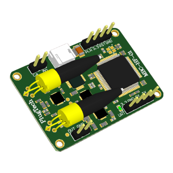
(1) Product Structure
No.
Name
1
Photodiode1
External Optical Feedback Input ( Laser channel )
2
Photodiode2
External Optical Feedback Input ( Modulator channel )
3
Ca An pins
Modulator's Internal photodiode Input
4
Power Connector
Controller's power supply connector
5
RST Pin
Operation for resetting controller
6
PLR Pin
Operation for polar selection
7
3.3 Pin
3.3V reference voltage of UART interface
GND TX RX Pins
UART interface for communication
8
OUT GND Pins
Controller's bias Output
9
M2 Mounting Hole
Controller's mounting hole
Constantly on: Working under tracking state
10
LED
On-off or off-on every 0.2s:
On-off or off-on every 1s: Controller's feedback input power is too weak
On-off or off-on every 3s: Controller's feedback input power is too strong
(2) Product Operating and Storage Information
Parameter
Positive power voltage
Positive power current
Negative power voltage
Negative power current
Modulator Channel Input optical power
Laser Channel Input optical power
Operating temperature
Storage temperature
MBC-HF Controller Operating Instruction
Describe
Initializing
and searching for controlling point
Min
Typ
+14.5
+15
20
-15.5
-15
2
-26
-26
-10
-20
3
2
1
9
Max
Unit
+15.5
V
30
mA
-14.5
V
4
mA
2
dBm
2
dBm
50
℃
80
℃
5
6
4
8
Figure1. Product Structure
7
10
Advertisement
Table of Contents

Subscribe to Our Youtube Channel
Related Manuals for PlugTech MBC-HF


Summary of Contents for PlugTech MBC-HF
- Page 1 MBC-HF Controller Operating Instruction (1) Product Structure Name Describe Photodiode1 External Optical Feedback Input ( Laser channel ) Photodiode2 External Optical Feedback Input ( Modulator channel ) Ca An pins Modulator’s Internal photodiode Input Power Connector Controller’s power supply connector...
- Page 2 (3) System Setup Instruction Figure 2. System diagram with controller’s on-board photodiode Figure 3. System diagram with modulator’s internal photodiode Depending on the different systems, the controller can be connected to the system as shown in Figure 2 or Figure 3. Here are the setup steps: Setp1.
- Page 3 Setp2. Setup controller’s feedback input (Modulator channel) Note: User should only choose one of the feedback method between controller’s on-board photodiode or modulator’s internal photodiode. Using controller’s on-board photodiode as feedback input: Choose an appropriate optical coupler to ensure the modulator channel feedback optical power are within the range indicated in the Product Operating Information table.
- Page 4 (4) Operating manual ⚫ Set MBC-HF to work in Q+ point ⚫ Set MBC-HF to work in Q- point (1) Connect controller’s output and feedback input properly (1) Connect controller’s output and feedback input properly (2) Keep PLR pins not connected.
- Page 5 (5) Cautions ⚫ Do not reverse the V+ and V- power pins, otherwise it will cause permanent damage to the controller. ⚫ ESD sensitive, please pay attention to human static electricity when operating. ⚫ Please provide the correct power supply voltage to avoid interfering with the operation of the controller or damaging it. ⚫...
- Page 6 (6) PowerBoard Operation Instruction(Optional) (1)Production Instruction 标识 名称 描述 M2 Mounting Hole Powerboard’s Mounting Hole OUTPUT Output voltage ± 15V Switch Control Powerboard’s Status Show Powerboard’s Status EARTH pin Ground pin INPUT1 +5V Input1 Input selection port Connection between input 1 and + 5V: INPUT1 as the input Connection between input 2 and + 5V:...
- Page 7 Version Content Date 1.0.0 First Release 2020/11/19 1.0.1 Add powerboard’s operation Instruction 2021/1/12...
Need help?
Do you have a question about the MBC-HF and is the answer not in the manual?
Questions and answers