Table of Contents
Advertisement
Quick Links
- 1 Installation Instructions
- 2 Connecting to Power
- 3 Pressurizing the Datasmart Manifold System
- 4 Wifi, Registration Code, Telemetry Configuration, User Selectable Features, System Parameters, User Selectable Features
- 5 Appendix B - Datasmart Wiring Diagram
- 6 Appendix D - Piping and Instrumentation (P&ID) Diagram
- 7 Appendix E - Datasmart Model 763 Gui Instructions
- Download this manual
Advertisement
Table of Contents

Related Manuals for Harris DataSmart 763


Summary of Contents for Harris DataSmart 763
- Page 1 Model 763 DataSmart Programmable Fully Automatic Manifold w/Telemetry Installation & Operation manual...
-
Page 2: Table Of Contents
CONTENTS Safety Guidelines……………………………………………………………………………….3 User Responsibility…………………………………………………………………………….4 Introduction To The Model 763 DataSmart Gas Distrubution System………………..5 …………………………………………………………….…………………….5 Features …………………………………………………………………… 6 Check Back Feature ………………………………………………….……………… 6 Economizer Function Installation Instructions…………………………………………………………….………….6 ………………………………………………………………………..7 Reference Material ……………………………………………………….………..7 Preparing For DataSmart ………………………………………………….……...8 General Installation Guidelines ……………………………………………………………………8 Mounting Instructions Attaching Cylinders…………………………………………………………………………….9 ……………………………………………………………9 For A Two Cylinder Manifold... -
Page 3: Safety Guidelines
• If product appears damaged in any way, do not use and contact Harris Products Group Technical Service. • Consult the cylinder distributor for the proper use of cylinders and for any restrictions on their use (such as flow rate and temperature requirements). -
Page 4: User Responsibility
Compressed Gas Association, 3 USER RESPONSIBILITY Service to this product should only be performed by HARRIS PRODUCTS GROUP.. Requests for service may be made through HARRIS CUSTOMER SERVICE. HARRIS accepts no responsibility for damage or injury if this product is modified in any way. HARRIS assumes/accepts no liability or responsibility for damage to individuals or equipment that may occur when using this product. -
Page 5: Introduction To The Model 763 Datasmart Gas Distrubution System
This integrated telemetry system also has the capability to send messages and alerts via email or SMS. Remote monitoring is a subscription based service that is available from The Harris Products Group. FEATURES •... -
Page 6: Check Back Feature
CHECK BACK FEATURE When using liquid cylinders, it is not uncommon for the primary side pressure to drop below the switchover point even if there is still a significant amount of gas left in the cylinder. This could be caused by an increase in downstream demand during peak gas usage, or, when the liquid volume in the cylinder becomes low. -
Page 7: Installation Instructions
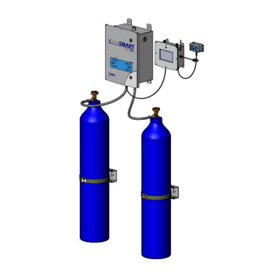
The above Figure 1 shows a typical installation with critical mounting dimensions. The Touchscreen Control Box can be mounted in close proximity to the Mechanical Enclosure. The Remote A/V Alarm Box can be mounted up to 200 feet away with the proper cable. Contact Harris Technical Service for more information. -
Page 8: Preparing For Datasmart
Touchscreen Control Box are designed with a Class 1, Division 2 NEMA enclosure and can be used for certain flammable gases. However, the system must be installed in a well ventilated location. 8. If product appears damaged in any way, do not use and contact The Harris Products Group Technical Service. -
Page 9: Attaching Cylinders
supplied is 10 ft. ATTACHING CYLINDERS The below safety guidelines should always be followed when handling compressed gas cylinders. 1. Handle cylinders carefully and only with valve caps screwed on. The cap will reduce the chance that the cylinder valve will break off if the cylinder is accidentally dropped or falls over. The cap also protects the cylinder valve from damage, which could cause leaky connections. - Page 10 Figure 2 – Two Cylinder Setup Manifold for more than two (2) cylinders Harris uses a modular header system for attaching multiple cylinders to the DataSmart manifolds (Ref. Figure 4). See Figure 3 for proper installation. The modular design allows greater flexibility for expansion and/or re-configuration of your multi-cylinder gas manifold.
-
Page 11: Manifold For More Than Two Cylinders
The header manifold is to be attached to a wall or other secure structure. Each valve will have a typical distance of either 5” or 10” from center to center depending on length of tube being used. The header assembly does not come with mounting hardware as the customer should choose fasteners appropriate for the mounting surface. -
Page 12: Pressurizing The Datasmart Manifold System
4. Do not torque any connection to greater than 60 ft-lbs. If leaks cannot be eliminated, contact your distributor or Harris Products Group Technical Service. DATASMART OPERATION INSTRUCTIONS 1. Connecting to Power a. -
Page 13: Datasmart Initial Setup
2. DataSmart Initial Setup a. Follow the steps below to configure the DataSmart for first-time use. Initial configuration values may be changed at any time. When the system starts up for the first time it will present a list of steps that must be taken before it will be fully functional. - Page 14 Figure 6 – Machine Name Screen 3. Configure Wi-Fi: Select the appropriate SSID (Wi-Fi Network Name) to allow connectivity to the DataSmart server. Enter the password and press OK to save. An active Wi-Fi connection is required to complete this step and to initialize the unit. If the DataSmart machine is unable to connect to a Wi-Fi network, it is recommended to turn the power off, then re-start the machine and return to the Configure Wi-Fi step.
- Page 15 Figure 8 – Registration Code 5. Telemetry Configuration: Select the appropriate configuration for your setup: a. AMS is the integrated telemetry system (recommended) b. Standalone telemetry with integrated sensor (user will connect using DataSmart sensors) c. Standalone telemetry with end-user sensors (user will connect their sensors) 6.
- Page 16 Figure 9 – Units and System Priority d. The following parameters must be selected and programmed on initial setup: 1. Choose Pressure Cylinder, Liquid Dewar, Cylinder Bank or Bulk system from the drop-down menu for both right and left sides. Figure 10 –...
-
Page 17: Datasmart Production Analytics
From your computer or mobile device, go to https://DataSmart.harrisproductsgroup.com/login to access and set up the analytics. You will have to contact Harris Products Group Customer Service at 800-241-0804 Option 2 to set up your account and register. Once your subscription service has been activated, follow the directions on the web application to set up messages and alerts based on your desired conditions at the gas manifold. -
Page 18: Appendix A - Cloud-Based Architectur/Security And Data Storage
APPENDIX A Cloud-Based Architecture DataSmart is a cloud-based system. This means that there is no dedicated computer required in your company to collect and store the data. Each machine requires a wireless internet connection in order to report production data. DataSmart initiates the transfer of information through a firewall to the data center. Data is transferred directly from DataSmart. -
Page 19: Appendix B - Datasmart Wiring Diagram
APPENDIX B Wiring Diagram pg. 19... -
Page 20: Appendix C - Troubleshooting Guide
System switches back and forth Switchover pressures not set properly guidelines on where switchover pressures should be More cylinders may need to be added; contact Harris System not sized correctly for liquid dewars Technical Service for recommendations. Cannot access DataSmart Web No subscription Contact Harris Customer Service to set up service. -
Page 21: Appendix D - Piping And Instrumentation (P&Id) Diagram
Appendix D Piping and Instrumentation (P&ID) Diagram... -
Page 22: Appendix E - Datasmart Model 763 Gui Instructions
Model 763 DataSmart GUI Instructions Overview The Model 763 DataSmart onboard GUI will allow users to update configuration settings, view operational parameters, and view basic analytical data. Using an internet connection through Wi-Fi, the controller can optionally allow for remote administration and mobile/email operational alerts, as well as data transmission and analysis. The system will require an internet connection for user administration, initial configuration, and data transmission. - Page 23 Splash Screen This screen is displayed every time the system starts up. *Note* Actual Model name will change – this is a placeholder Initial Setup/Configuration On the initial startup, the system will prompt the user to set the Machine Name, select a Wi-Fi network, validate the registration code for the subscription, and set the operation mode parameters.
- Page 24 Machine Initialization As the user completes each step, the system will change the ellipsis button to a static indicator (green check mark). Step 1 QA Mode Password: AMS$QT#2019, Erase Code/Password(HPG$ERASE#NFLASH) Pressing returns the user to the previous screen without saving changes. Pressing Enter saves the configuration. A confirmation message shall be presented to the user.
- Page 25 Step 2...
- Page 26 Pressing returns the user to the previous screen without saving changes. Pressing Enter saves the configuration. A confirmation message shall be presented to the user. Note: If the selected Wi-Fi (access point) don’t have the password(Open Network) then the user should not fill anything under the Enter Password field (i.e.
- Page 27 Pressing returns the user to the previous screen without saving changes. Pressing Enter saves the configuration. A confirmation message shall be presented to the user.
- Page 28 When the registration code is validated during initial setup, the machine will transmit the following information to the server: Registration code Machine Name Machine Serial Number This data will be sent in one string with individual values separated by pipes using the format Registration Code|Machine Name|Serial Number Example: ...
- Page 29 Step 4 Telemetry Configuration selection options: Integrated system with Gas Block NG960 Standalone telemetry with integrated sensor Standalone telemetry with end-user selected sensors...
- Page 30 Note: The Telemetry configuration is setable through the Dip switch connected on the Control board and based on the Dip switch configuration setting the Telemetry type will be automaticall available under the dropdown. User have to verify the telemetry type and press enter. Dip Switch Configuration in below table: SlNo Dip Switch 1...
- Page 32 System Parameters – initial screen The first step is to set the Unit of Measurement (radio buttons): If the user presses the Imperial/US radio button to change the Unit of measurement then new screen will popup as shown below...
- Page 33 Available UoM in Imperial For Pressure: PSIG only For Flow SCFH SCFM...
- Page 34 If the user press at the Metric radio button to change the Unit of measurement then new screen will popup as shown below Available UoM in Metrics For Pressure: BAR, kPa,MPa For Flow LPH, LPM,M3/h...
- Page 35 The second step is to select System Priority: LEFT BANK RIGHT BANK FIRST IN FIRST OUT (FIFO) When the user selects a bank (Left or Right), they will automatically be taken into the corresponding screen to configure. Upon pressing DONE they will then be taken to the opposite bank screen to configure.
- Page 36 Ammonia Carbon Monoxide Methane Acetylene Nitrogen Dioxide Liquid Dewar and Bulk System: Nitrogen Oxygen Carbon Dioxide Argon Pressing returns the user to the previous screen without saving changes. Press NEXT to continue.
- Page 37 If the user selects Pressure Cylinder or Cylinder Bank with Telemetry option 1 (Integrated system with Gas Block NG960) or 2(Standalone telemetry with integrated sensor): If the user selects Pressure Cylinder or Cylinder Bank with Telemetry option 3 (Standalone telemetry with end-user selected sensors): Cylinder Capacity ...
- Page 38 4500 6000 Pressing BACK returns the user to the previous screen without saving changes. Switchover pressure is changed by pressing to decrease and to increase. Pressure value increases and decreases in increments of 12. Default pressure is set to 200. Minimum allowable pressure is 70; maximum allowable pressure is 2400.
- Page 39 If the user selects Liquid Dewar or Bulk System with Telemetry option 1 (Integrated system with Gas Block NG960) or 2(Standalone telemetry with integrated sensor): If the user selects Liquid Dewar or Bulk System with Telemetry option 3 (Standalone telemetry with end-user selected sensors): Pressing BACK returns the user to the previous screen without saving changes.
- Page 40 Switchover pressure is changed by pressing to decrease and to increase. Pressure value increases and decreases in increments of 12. Default pressure is set to 200. Minimum allowable pressure is 70; maximum allowable pressure is 2400. Container Size and Daily Decay Venting Allowance (and Sensor Readings for config 3) are required fields. Default Switchover Pressure (200) can be used.
- Page 41 If the touch is detected at any of the edit box (Container Size: or at Daily Decay Venting Allowance%[x.x]: ) then the new screen will pop up as shown below, user will enter the value corresponding to the container size and daily decay and will press the enter.
- Page 42 If the user selects a non-bulk gas source on the non-primary side, the user needs to be notified that it's not a desired setting. So, for example, the user selects LEFT BANK as primary, then selects Liquid Dewar or Bulk Cylinder as the gas source on the right side.
- Page 43 Until both Banks are configured, the system will reflect the bank status with a check mark: Once the two banks are configured, the system will begin gas flow. Delivery Pressure will be displayed. The user must press CONFIRM to verify that the Delivery Pressure is correct:...
- Page 44 Once the Delivery Pressure has been confirmed, the confirmation light appears green; the configuration is complete and the DONE button is made available. When the user presses DONE, the system shall save the configuration and return the user to the main "wizard" to close out system initiation.
- Page 45 Pressing DONE completes the process and directs to the Operation Mode screen. Operation Mode Showing Pressure Cylinder graphics Machine Name...
- Page 46 Cylinder Bank graphics Machine Name Liquid Dewar graphics Machine Name Bulk System graphics...
- Page 47 Machine Name Operation Mode will display the configuration settings as set by the user: Priority; Gas Source for each bank. A graphic will display for each bank that wil correspond to the approximate available gas in each bank: 0-20%; 21 – 40%; 41-60%; 61-80%;...
- Page 48 Pressing EDIT allows an authenticated user to change the System Priority and/or bank settings: Pressing returns the user to operation mode without saving changes. Pressing DONE saves the configuration and returns the user to the Operation Mode screen. Pressing either of the ellipsis buttons beside a bank edits the corresponding bank.
- Page 49 Note: Banks are edited independently once initial configuration is complete (a user may want to only edit one bank). The edit screens are the same as the initial config screens and the rules are the same. The only difference is that the configured values are displayed for the fields.
- Page 51 If the user presses SYSTEM CONFIG from the Operation Mode screen, they can change system configuration settings. Access to this area requires a valid user name/password. Three updates are made 1- Username Password Update 2- Telemetry Configuration 3- Firwmare Update Press DONE to return to Operation Mode.
- Page 52 Edit Machine Name There is no option in the system to check the serial number of the machine, hence the below screen is removed and previously used screen to enter the machine name is used here. Below screen is not used QA Mode Password: AMS$QT#2019, Erase Code/Password(HPG$ERASE#NFLASH) Edit WiFi Configuration:...
- Page 54 Edit Username Password: Edit Frame Generation Frequency: Edit Telemetry Type:...
- Page 55 Pressing returns the user to the previous screen.
- Page 56 Firmware Update: If the Edit button for firmware update is pressed then below screen will appear, and user have to press OK button in order to start the firmware download After press on the OK button below screen will appear with progress of the file being downloaded...
- Page 57 Once the file is downloaded then Machine will restart and below screen will appear with the progress of file being installed After the installation is completed then below screen will appear and user have to press on the Close Button in order to resume the firmware operation...
- Page 58 Fonts: All text: Eurostile Pressure indicators (digital number fonts): LCD Light (can be represented by equivalent digital number font) Colors: Blue: HEX #0053A0 Grey: HEX #888888...
Need help?
Do you have a question about the DataSmart 763 and is the answer not in the manual?
Questions and answers